Page 2475 of 4264

ENGINE MECHANICAL (C24SE) 6A-55
OPERATIONS ON REMOVED ENGINE
Crankshaft
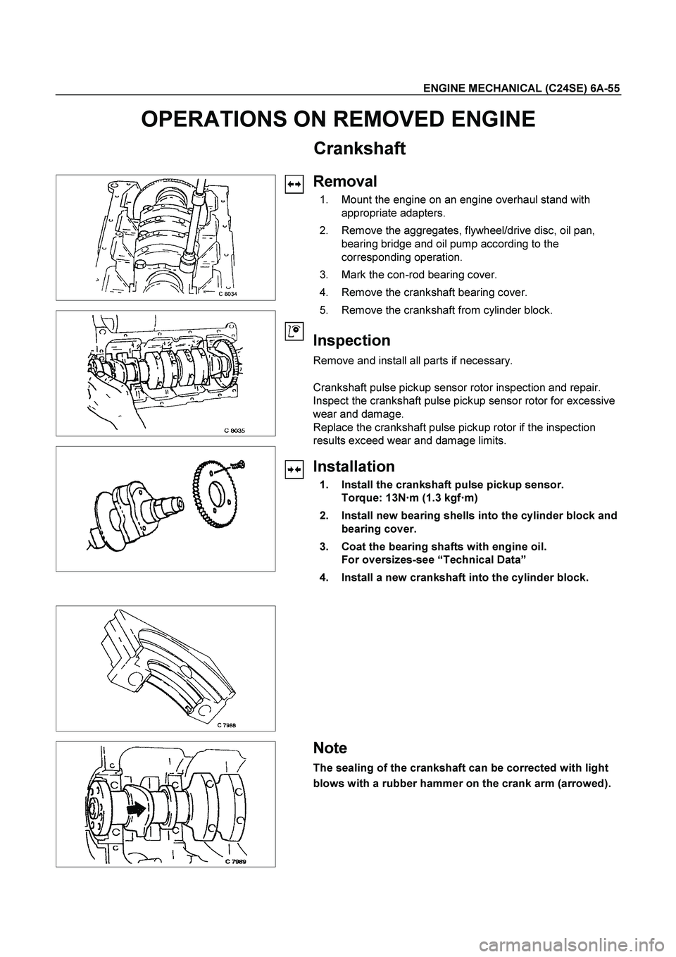
Removal
1. Mount the engine on an engine overhaul stand with
appropriate adapters.
2. Remove the aggregates, flywheel/drive disc, oil pan,
bearing bridge and oil pump according to the
corresponding operation.
3. Mark the con-rod bearing cover.
4. Remove the crankshaft bearing cover.
5. Remove the crankshaft from cylinder block.
Inspection
Remove and install all parts if necessary.
Crankshaft pulse pickup sensor rotor inspection and repair.
Inspect the crankshaft pulse pickup sensor rotor for excessive
wear and damage.
Replace the crankshaft pulse pickup rotor if the inspection
results exceed wear and damage limits.
Installation
1. Install the crankshaft pulse pickup sensor.
Torque: 13N�
�� �m (1.3 kgf�
�� �m)
2. Install new bearing shells into the cylinder block and
bearing cover.
3. Coat the bearing shafts with engine oil.
For oversizes-see “Technical Data”
4. Install a new crankshaft into the cylinder block.
Note
The sealing of the crankshaft can be corrected with light
blows with a rubber hammer on the crank arm (arrowed).
Page 2489 of 4264
ENGINE MECHANICAL (C24SE) 6A-69
FUEL INJECTION SYSTEM
MAP SENSOR
Removal
1. Disconnect the battery cable.
2. Disconnect the electrical connector from the sensor.
3. Remove the mounting bolts securing the sensor to the manifold.
4. Remove the sensor from the intake manifold.
Installation
1. Push MAP sensor into the manifold.
2. Install the mounting bolts and tighten them.
3. Connect electrical connector.
4. Connect the battery cable.
Pressure Regulator
Removal
1. Remove vacuum hose.
2. Remove fuel hoses.
3. Remove pressure regulator.
Installation
1. Install pressure regulator.
2. Install fuel hoses.
3. Install vacuum hoses.
ECM (Engine Control Module)
Removal
(2.4L)
1. Disconnect the ECM connector.
2. Remove the four hex bolts and nuts.
3. Remove the ECM from the ECM bracket on engine.
Page 2490 of 4264
6A-70 ENGINE MECHANICAL (C24SE)
Installation
(2.4L)
1. Install the ECM to the ECM bracket on engine.
2. Tighten the four screws to the bracket.
3. Connect the connector.
ECT
Removal
1. Remove wiring harness plug and coolant temperature
sensor.
Tighten (Torque)
Temperature sensor to intake pipe - 10 N�
m (1.0 kgf�
m)
Wiring harness plug to temperature sensor
Inspection
Coolant level
Idle Air Control (IAC) Valve
Removal
1. Remove wiring harness plug, hose clamps and idle
speed adjuster.
Installation
1. Install idle speed adjuster, hose clamps and wiring
harness plug.
Ignition Coil
Removal
1. Remove 2 bolts, plug and ignition coil.
Installation
1. Install ignition coil, plug and bolts.
Page 2491 of 4264
ENGINE MECHANICAL (C24SE) 6A-71
Crank Position Sensor
Removal
1. Remove crank position sensor.
Installation
1. Install crank position sensor.
Page 2492 of 4264

6A-72 ENGINE MECHANICAL (C24SE)
FUEL INJECTOR
Removal
Caution: To reduce the risk of fire and personal injury, it is
necessary to relieve the fuel system pressure before
servicing the fuel system components.
Caution: After relieving the fuel system pressure, a small
amount of fuel may be released when servicing fuel lines
or connections. Reduce the chance of personal injury by
covering the fuel line fitting with a shop towel before
disconnecting the fittings. The towel will absorb any fuel
that may leak out. When the disconnect is completed,
place the towel in an approved container.
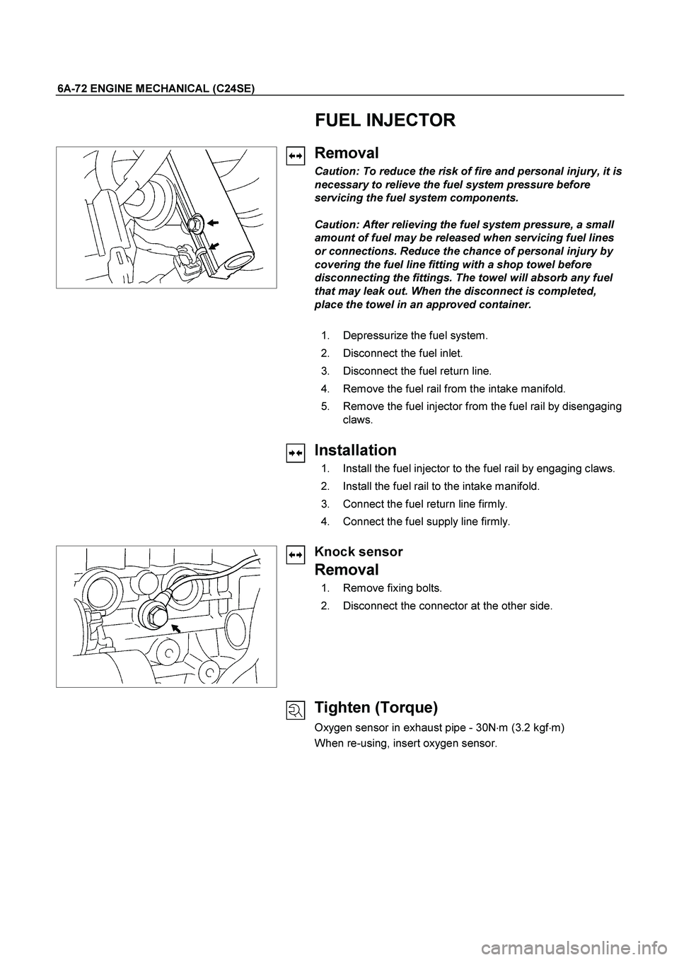
1. Depressurize the fuel system.
2. Disconnect the fuel inlet.
3. Disconnect the fuel return line.
4. Remove the fuel rail from the intake manifold.
5. Remove the fuel injector from the fuel rail by disengaging
claws.
Installation
1. Install the fuel injector to the fuel rail by engaging claws.
2. Install the fuel rail to the intake manifold.
3. Connect the fuel return line firmly.
4. Connect the fuel supply line firmly.
Knock sensor
Removal
1. Remove fixing bolts.
2. Disconnect the connector at the other side.
Tighten (Torque)
Oxygen sensor in exhaust pipe - 30N�
m (3.2 kgf�
m)
When re-using, insert oxygen sensor.
Page 2493 of 4264
ENGINE MECHANICAL (C24SE) 6A-73
Oxygen Sensor (If applicable)
Removal
1. Remove wiring harness plug.
2. Remove oxygen sensor from the front exhaust pipe.
Tighten (Torque)
Oxygen sensor in exhaust pipe - 30 N�
m (3.1 kgf�
m)
Throttle Valve Position Sensor
Removal
1. Remove wiring harness connector.
2. Remove throttle valve position sensor.
Installation
1. Install throttle valve position sensor.
2. Install wiring harness connector.
Accelerator Pedal and Cable
Removal
1. Remove pad stopper from pedal stop bolt.
Installation
1. Install pad stopper.
Inspection
Ensure that accelerator pedal is fully in idle position and
accelerator level at engine is in closed position.
Pull outer sleeve of accelerator cable towards pedal and check
that clip on sleeve is in slot nearest to grommet.
Reposition clip if necessary, and check that full throttle and idle
positions are obtained at engine lever.
Page 2497 of 4264

ENGINE MECHANICAL (C24SE) 6A-77
Cooling System
Radiator
Type: Cross-flow
Radiator core surface in cm
2: 2000
Cooling system capacity (in litres): 7.2
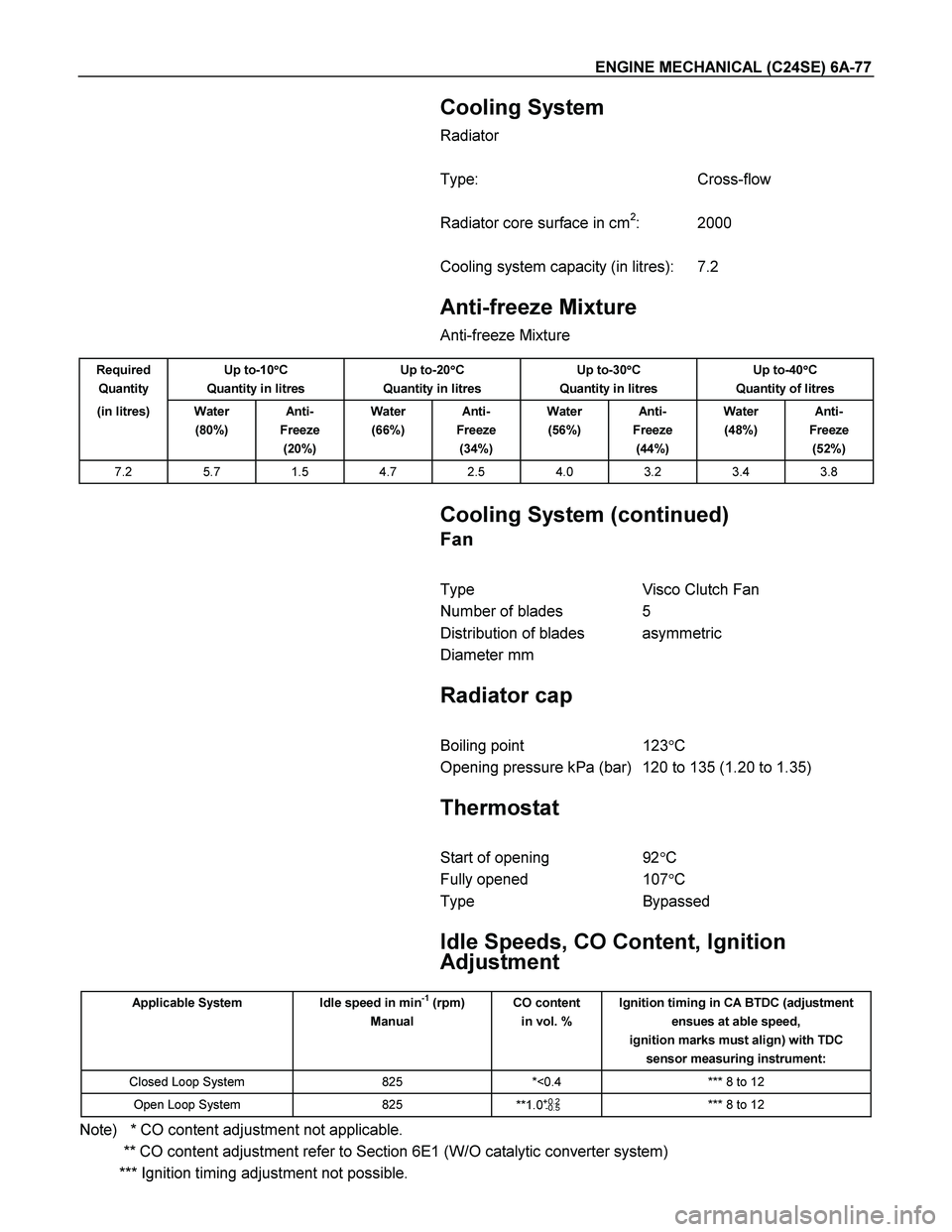
Anti-freeze Mixture
Anti-freeze Mixture
Required
Quantity Up to-10�
�� �C
Quantity in litres Up to-20�
�� �C
Quantity in litres Up to-30�
�� �C
Quantity in litres Up to-40�
�� �C
Quantity of litres
(in litres) Water
(80%) Anti-
Freeze
(20%) Water
(66%) Anti-
Freeze
(34%) Water
(56%) Anti-
Freeze
(44%) Water
(48%) Anti-
Freeze
(52%)
7.2 5.7 1.5 4.7 2.5 4.0 3.2 3.4 3.8
Cooling System (continued)
Fan
Type Visco Clutch Fan
Number of blades 5
Distribution of blades asymmetric
Diameter mm
Radiator cap
Boiling point 123�C
Opening pressure kPa (bar) 120 to 135 (1.20 to 1.35)
Thermostat
Start of opening 92�C
Fully opened 107�C
Type Bypassed
Idle Speeds, CO Content, Ignition
Adjustment
Applicable System Idle speed in min-1 (rpm)
Manual CO content
in vol. % Ignition timing in CA BTDC (adjustment
ensues at able speed,
ignition marks must align) with TDC
sensor measuring instrument:
Closed Loop System 825 *<0.4 *** 8 to 12
Open Loop System 825
**1.0+0.2
-0.5 *** 8 to 12
Note) * CO content adjustment not applicable.
** CO content adjustment refer to Section 6E1 (W/O catalytic converter system)
*** Ignition timing adjustment not possible.
Page 2515 of 4264
ENGINE COOLING 6B-5
Diagnosis
Engine Cooling Trouble
Condition Possible cause Correction
Engine overheating Low Engine Coolant level Replenish
Thermo mater unit faulty Replace
Faulty thermostat Replace
Faulty Engine Coolant temperature
sensor Repair or replace
Clogged radiator Clean or replace
Faulty radiator cap Replace
Low engine oil level or use of
improper engine oil Replenish or change oil
Clogged exhaust system Clean exhaust system or replace
faulty parts
Faulty Throttle Position sensor Replace throttle valve assembly
Open or shorted Throttle Position
sensor circuit Repair or replace
Damaged cylinder head gasket Replace
Loosen V-belt tension Adjust belt tension or replace.
Collapsed hoses Replace
Faulty Fan clutch Replace
Engine overcooling Faulty thermostat Replace
Engine slow to warm-up Faulty thermostat Replace
Thermo unit faulty Replace