Page 3566 of 4264
3D-10 REAR SUSPENSION
Reassembly
1. Apply grease to both faces of each leaf spring at
reassembly.
2. Set the leaf springs aligning the setting mark before
disassemble.
F03L100006
3. Assemble the leaf springs using a bench press.
4. Apply grease to the outside of the bushing.
Install a new center bolt and tighten it to the specified
torque.
Torque N
�m (kg
�m/lb
�ft)
29 (3.0/22)
5. Install the bushing using a bench press and a suitable
metal fitting.
Page 3573 of 4264

WHEELS AND TIRES 3E-1
SECTION 3E
WHEELS AND TIRES
TABLE OF CONTENTS
PAGE
Main Data and Specifications ........................................................................................... 3E- 2
Torque Specifications ....................................................................................................... 3E- 3
Special Parts Fixing Nuts and Bolts ............................................................................ 3E- 3
Wheels and Tires ...............................................................................................................3E- 4
General Description ...................................................................................................... 3E- 4
Servicing ........................................................................................................................ 3E- 6
Disassembly and Reassembly ..................................................................................... 3E- 7
Inspection and Repair................................................................................................... 3E- 8
Troubleshooting ................................................................................................................3E- 10
Page 3575 of 4264
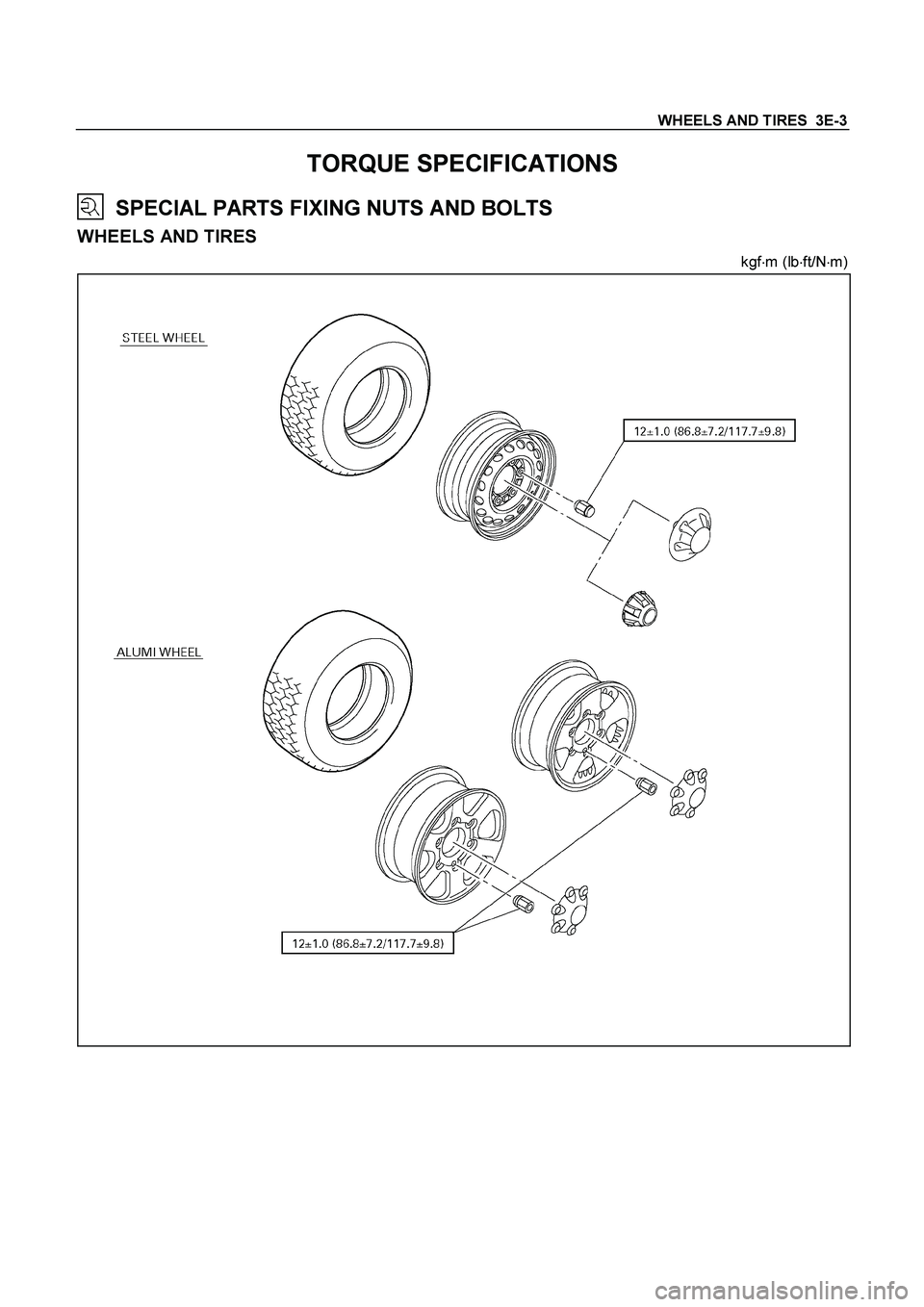
WHEELS AND TIRES 3E-3
TORQUE SPECIFICATIONS
SPECIAL PARTS FIXING NUTS AND BOLTS
WHEELS AND TIRES
kgf�
m (lb�
ft/N�
m)
Page 3578 of 4264
3E-6 WHEELS AND TIRES
SERVICING
Servicing refers to general maintenance procedures to be performed by qualified service personnel.
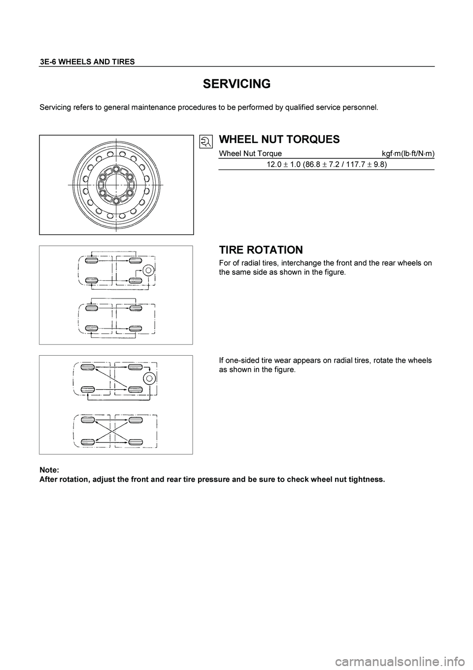
WHEEL NUT TORQUES
Wheel Nut Torque kgf�m(lb�ft/N�m)
12.0 � 1.0 (86.8 � 7.2 / 117.7 � 9.8)
TIRE ROTATION
For of radial tires, interchange the front and the rear wheels on
the same side as shown in the figure.
If one-sided tire wear appears on radial tires, rotate the wheels
as shown in the figure.
Note:
After rotation, adjust the front and rear tire pressure and be sure to check wheel nut tightness.
Page 3581 of 4264
WHEELS AND TIRES 3E-9
Important Operations
1. Tire Assembly
Align the match mark (approx. 10mm diameter paint mark) of
wheel with match mark (approx. 8mm diameter red paint mark)
of tire to assemble. If the match mark at wheel has
disappeared, align with air valve to assemble.
2. Wheel and Tire Assembly
3. Wheel Nut
Tighten wheel nuts in numerical order.
Wheel Nut Torque kgf�m (lb�ft/N�m)
12.0 � 1.0 (86.8 � 7.2 / 117.7 � 9.8)
Page 3590 of 4264
. REFER TO THE SRS
COMPONENT AND WIRING LOCATION VIEW IN
ORDER TO DETERMINE WHETHER YOU ARE")
7D-2 TRANSFER CASE
Service Precaution
WARNING: THIS VEHICLE HAS A SUPPLEMENTAL
RESTRAINT SYSTEM (SRS). REFER TO THE SRS
COMPONENT AND WIRING LOCATION VIEW IN
ORDER TO DETERMINE WHETHER YOU ARE
PERFORMING SERVICE ON OR NEAR THE SRS
COMPONENTS OR THE SRS WIRING. WHEN YOU
ARE PERFORMING SERVICE ON OR NEAR THE
SRS COMPONENTS OR THE SRS WIRING, REFER
TO THE SRS SERVICE INFORMATION. FAILURE TO
FOLLOW WARNINGS COULD RESULT IN
POSSIBLE AIR BAG DEPLOYMENT, PERSONAL
INJURY, OR OTHERWISE UNNEEDED SRS SYSTEM
REPAIRS.
CAUTION: Always use the correct fastener in the
proper location. When you replace a fastener, use
ONLY the exact part number for that application.
ISUZU will call out those fasteners that require a
replacement after removal. ISUZU will also call out
the fasteners that require thread lockers or thread
sealant. UNLESS OTHERWISE SPECIFIED, do not
use supplemental coatings (Paints, greases, or
other corrosion inhibitors) on threaded fasteners or
fastener joint interfaces. Generally, such coatings
adversely affect the fastener torque and the joint
clamping force, and may damage the fastener.
When you install fasteners, use the correct
tightening sequence and specifications. Following
these instructions can help you avoid damage to
parts and systems.
Page 3597 of 4264
TRANSFER CASE 7D-9
For A/T
261R300002
3.
Connect harness connectors and clip.
Connector: transfer switch, 2WD-4WD actuator,
speed sensor.
4. Install center exhaust pipe(5). (6VE1 only)
5.
Install rear propeller shaft (1) and front propelle
r
shaft (2)(3).
Torque: 63 N�
�� �m (6.4 kg�
�� �m/46 lb ft)
Page 3618 of 4264
7D-30 TRANSFER CASE
226R300005
30.
Temporarily install the speedometer drive gear to the
inside of the rear cover. Pay close attention to
installation direction.
31.
Use a press and the installer (9-8522-1268-0) to
install the rear output shaft ball bearings. Do not
drive the ball bearings into place with a hammer.
32.
Install the rear output shaft retaining ring.
33.
Place the oil pump in its specified position.
34.
Secure the pump strainer to the rear cover and
tighten the bolts to the specified torque.
Rear cover and transfer case bolt torque:
15 Nm (1.5 kgm/11 lb ft)
226R300010
35.
Apply Loctite FMD 127 to the mating surfaces of the
rear cover and the transfer case. Be sure that the
Loctite is evenly applied to the inside surfaces of the
bolt holes with no gaps.
Legend
(1) Oil Pump ASM
(2) Wire Snapring
(3) Retaining Ring
(4) Ball Bearing
(5) Speedometer Gear Drive Gear
(6) Rear Cover
Legend
(1) Wire Snapring

 of
wheel with match mark (approx. 8mm diameter red paint mark)
of tire to a")
. (6VE1 only)")
