Page 3538 of 4264

3C-46 FRONT SUSPENSION
Inspection and Repair
Make necessary correction or parts replacement if
wear, damage, corrosion or any other abnormal
condition are found through inspection.
Check the following parts:
�
Lower control arm
�
Bushing
Installation
1. Install rear bushing by using installer 5-8840-2124-
0.
Front
901RW053
2. Install front bushing by using installer 5-8840-
2123-0.
Front
901RW156
3. Install lower ball joint bolt.
4. Install torsion bar arm bolt.
5. Install lower control arm.
6. Install rear bolt.
7. Install cam bolt the hole and projection are
upward.
8. Install lower ball joint and tighten it to the specified
torque (12).
Torque: 127 N�
�� �m (12.9kg�
�� �m/94 lb ft)
9. Install shock absorber and tighten it to the
specified torque (13).
Torque: 93 N�
�� �m (9.5kg�
�� �m/69 lb ft)
10. Install stabilizer link and tighten it to the specified
torque (14).
Torque: 50 N�
�� �m (5.1kg�
�� �m/37 lb ft)
11. Install torsion bar arm bracket and tighten it to the
specified torque.
Torque: 116 N
�
�� �m (11.8kg
�
�� �m/85 lb ft)
12. Install Torsion bar, refer to Torsion Bar in this
section.
13. Install rear nut and tighten lower link nut finger-
tight (4).
NOTE: Apply oil to the thread.
NOTE: Tighten the nut or bolt with the parts in the
position shown in the illustration below.
Buffer clearance: 29.7 mm (1.17 in)
Torque: 235 N�
�� �m (24.0kg�
�� �m/174 lb ft)
450R100002
Page 3539 of 4264
FRONT SUSPENSION 3C-47
14. Install cam plate and nut then tighten lower link nut
finger-tight.
NOTE: Apply oil to the thread.
NOTE: Tighten the nut (3) or bolt with the parts in the
position shown in the illustration below.
Buffer clearance: 29.7 mm (1.17 in)
Torque: 186 N�
�� �m (19.0kg�
�� �m/137 lb ft)
NOTE: Adjust the trim height. Refer to Front En
d
Alignment Inspection and Adjustment in Steering
section.
450R100002
Page 3541 of 4264

FRONT SUSPENSION 3C-49
CAUTION: Be careful not to damage the ball joint
boot.
RTW340SH000401
4. Remove bolt and nut.
5. Remove upper ball joint.
Inspection and Repair
Make necessary parts replacement if wear, damage,
corrosion or any other abnormal conditions are found
through inspection.
�
Inspect the lower end boot for damage or grease
leak. Move the ball joint as shown in the figure to
confirm its normal movement.
�
Inspect screw/taper area of ball for damage.
�
If any defects are found by the above inspections,
replace the ball joint assembly with new one.
450RS023
�
After moving the ball joint 4 or 5 times, attach nut
then measure the preload.
Starting torque: 1.3–3.2 N�
�� �m (0.13-0.33kg�
�� �m/0.9-
2.4 lb ft)
450RS024
If the above limits specified are exceeded, replace the
ball joint assembly.
Installation
1. Install upper ball joint.
2. Install bolt and nut (1), then tighten them to the
specified torque.
Torque: 57 N�
�� �m (5.8kg�
�� �m/42 lb ft)
3. Install nut and cotter pin, then tighten the nut to the
specified torque with just enough additional torque
to align cotter pin holes. Install new cotter pin (3).
Torque: 98 N�
�� �m (10.0kg�
�� �m/72 lb ft)
Page 3543 of 4264

FRONT SUSPENSION 3C-51
CAUTION: Be careful not to damage the ball joint
boot.
901RW271
7. Remove nut.
8. Remove bolt.
9. Remove lower ball joint.
Inspection and Repair
Make necessary parts replacement if wear, damage,
corrosion or any other abnormal condition are found
through inspection.
�
Inspect the lower end boot for damage or grease
leak. Move the ball joint as shown in the figure to
confirm its normal movement .
�
Inspect screw/taper area of ball for damage.
� If any defects are found by the above inspections,
replace the ball joint assembly with new one.
450RS026
� After moving the ball joint 4 or 5 times, attach nut
then measure the preload.
Starting torque: 2.5-6.4 N�
�� �m (0.25-0.65kg�
�� �m/1.8-
4.7 lb ft)
450RS024
�
If the above limits specified are exceeded, replace
the ball joint assembly.
Installation
1. Install lower ball joint.
2. Install bolt.
3. Install nut (3) and tighten it to the specified torque.
Torque: 127 N�
�� �m (12.9kg�
�� �m/94 lb ft)
4. Install ball joint nut, then tighten it to the specified
torque with just enough additional torque to align
cotter pin holes. Install new cotter pin (4).
Torque: 147 N�
�� �m (15.0kg�
�� �m/108 lb ft)
Page 3544 of 4264
3C-52 FRONT SUSPENSION
Bump Rubber
Bump Rubber and Associated Parts
RTW340MF001001
Legend
(1)
Bolt
(2)
Bump Rubber
Removal
1. Raise the vehicle and support the frame with
suitable safety stands.
2. Remove bolt.
3. Remove bump rubber.
Inspection and Repair
Make necessary correction or parts replacement if
wear, damage, corrosion or any other abnormal
condition are found through inspection.
Check the following parts :
� Bump Rubber
Installation
1. Install bump rubber.
NOTE: Arrow points to be vehicle outer side of afte
r
assembly to vehicle.
2. Install bolt (1), then tighten it to the specified
torque.
Torque: 42 N�
�� �m (4.3kg�
�� �m/31 lb ft)
Page 3557 of 4264

REAR SUSPENSION 3D-1
SECTION 3D
REAR SUSPENSION
TABLE OF CONTENTS
PAGE
Main Data and Specifications...........................................................................................3D- 2
Torque Specifications........................................................................................................ 3D- 3
Rear Suspension................................................................................................................3D- 4
General Description ...................................................................................................... 3D- 4
Leaf Spring and Shock Absorber ..................................................................................... 3D- 5
Leaf Spring and Associated Parts ............................................................................... 3D- 5
Removal .........................................................................................................................3D- 6
Inspection and Repair ................................................................................................... 3D- 7
Installation ..................................................................................................................... 3D- 8
Leaf Spring Assembly ....................................................................................................... 3D- 9
Disassembly .................................................................................................................. 3D- 9
Inspection and Repair ................................................................................................... 3D- 9
Reassembly ................................................................................................................... 3D- 10
Troubleshooting................................................................................................................. 3D- 11
Page 3559 of 4264
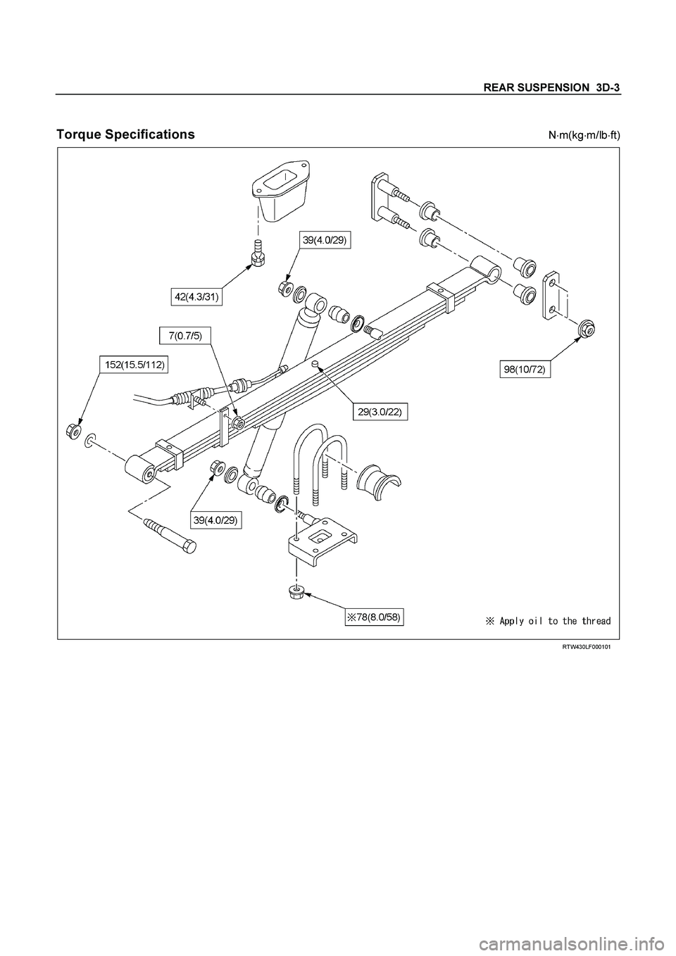
REAR SUSPENSION 3D-3
Torque Specifications
N
�m(kg
�m/lb
�ft)
RTW430LF000101
Page 3564 of 4264
 and bolt and tighten it to the
specified torque.
Torque N�m (kg�m/lb�ft)
42 (4.3/31)
2. Install the leaf spring (14).
�")
3D-8 REAR SUSPENSION
Installation
1. Install the bump rubber (15) and bolt and tighten it to the
specified torque.
Torque N�m (kg�m/lb�ft)
42 (4.3/31)
2. Install the leaf spring (14).
� The leaf spring assembly should be installed so that the
built-in rubber bush is toward the front.
� Align the holes of the spring eye and frame bracket.
� Insert the spring pin (13) toward vehicle inner side
through the frame bracket holes and the spring bush
hole.
� Tighten the nut (12) a little and after the vehicle is
lowered, tighten it to the specified torque.
Torque N
�m (kg
�m/lb
�ft)
152 (15.5/112)
RTW340LF000101
� Apply rubber grease to inside and outside of the rubber
bushing.
� Install the rubber bushings (11) into the hole of the
frame side bracket and the spring rear eye.
� Install the shackle pin (10) and shackle plate (9).
� Tighten the nuts (8) a little and after vehicle is lowered,
tighten it to the specified torque.
Torque N�m (kg�m/lb�ft)
98 (10/72)
3. Support the lower clamp (7) under the leaf spring.
4. Apply oil to the thread portion of U bolt (6).
Install the U bolt and seat on the rear axle and insert the U
bolt in the lower clamp holes.
5. Tighten the nut (5) to the specified torque.
Torque N�m (kg�m/lb�ft)
78 (8.0/58)
6. Install the shock absorber (4) and inner washer on the
lower clamp pin and frame side pin.
7. Install the washer and nut (3) on the frame side pin and
tighten the nut to the specified torque.
Torque N�m (kg�m/lb�ft)
39 (4.0/29)
8. Install the washer and nut (2) on the lower clamp pin and
tighten the nut to the specified torque.
Torque N�m (kg�m/lb�ft)
39 (4.0/29)
9. Install the parking brake cable (1) on the leaf spring and
tighten the nut at its bracket.
Torque N
�m (kg
�m/lb
�ft)
7 (0.7/5)
 or bolt with the parts in the
position sho")

Bolt
(2)
Bump Rubber
Removal
1. Raise the vehicle and support the frame with
sui")