Page 4200 of 4264
7A4-26 UNIT REPAIR (JR405E)
No. Valve
nomenclature Diameter
(mm / in) Length
(mm / in)Configuration
14 Pressure relief ---- ----
15 Pressure
regulator 16.0 /
0.630 89.5 /
3.524
16 Low and reverse
brake fail (A) 10.0 /
0.394 52.0 /
2.047
17 Fail 12.0 /
0.472 53.5 /
2.106
18 Low and reverse
brake amp 12.0 /
0.472 55.5 /
2.185
19 2 – 4 brake fail
(A) 10.0 /
0.394 65.5 /
2.579
20 Low clutch amp
(B) 12.0 /
0.472 53.0 /
2.087
21 Torque
converter relief 10.0 /
0.394 37.4 /
1.472
22 2 – 4 brake
solenoid
accumulator 14.0 /
0.551 19.5 /
0.768
23 High clutch
accumulator 10.0 /
0.394 31.0 /
1.220
Page 4201 of 4264
 7A4-27
Spring specifications
No. Valve nomenclature Free length
(mm / in) Outside
diameter (mm
/ in) Linear
diameter (mm
/ in) Number of
coils
14 Pressure relief 49.")
UNIT REPAIR (JR405E) 7A4-27
Spring specifications
No. Valve nomenclature Free length
(mm / in) Outside
diameter (mm
/ in) Linear
diameter (mm
/ in) Number of
coils
14 Pressure relief 49.0 / 1.929 7.6 / 0.299 1.1 / 0.043 17.3
15 Pressure regulator 30.5 / 1.201 14.0 / 0.551 1.4 / 0.055 5.7
16 Low and reverse brake fail (A) 22.0 / 0.866 7.0 / 0.276 0.6 / 0.024 10.0
17 Fail 23.0 / 0.906 11.0 / 0.433 0.5 / 0.020 13.2
18 Low and reverse brake amp 19.5 / 0.768 7.9 / 0.311 0.5 / 0.020 6.9
19 2 – 4 brake fail (A) 24.8 / 0.976 8.5 / 0.335 0.9 / 0.035 7.8
20 Low clutch amp (B) 26.0 / 1.024 11.0 / 0.433 0.5 / 0.020 6.9
21
Torque converter relief More than 47.2
/ 1.858 9.2 / 0.362 1.6 / 0.063 20.2
22 2 – 4 brake solenoid accumulator 31.4 / 1.236 9.8 / 0.386 1.3 / 0.051 9.3
23 High clutch accumulator 51.0 / 2.008 6.5 / 0.256 0.8 / 0.031 23.5
Oil pressure switch
Apply compressed air (392 kPa/4.0 kg/cm2) to the oil pressure
switch to check the oil pressure switch continuity between the
connector and screw.
244L300011
Oil temperature sensor (harness assembly)
Check the oil temperature sensor resistance between harness
terminals 7 and 6 (ground).
Oil temperature sensor resistance: 2,400�
�� �2,600 ohms
(20�
�� �)
Solenoid
Measure the resistance of each solenoid.
Resistance:
Brown connector – 3.0�
�� �3.4 ohms (20�
�� �C)
Gray connector – 12.0�
�� �13.2 ohms (20�
�� �C)
White connector – 12.2�
�� �13.4 ohms (20�
�� �C)
Reassembly steps
� Coat the parts with ATF before installing them.
� Install the control valve to the control valve lower body.
� Install the oil filter to the control valve lower body.
Page 4206 of 4264
7A4-32 UNIT REPAIR (JR405E)
CLUTCH PACK (REVERSE AND
HIGH CLUTCH ASSEMBLY)
01R&H17
Legend
1. Reverse and high clutch drum
2. Seal ring (reverse clutch)
3. Lip seal (reverse clutch)
4. Reverse clutch piston
5. Seal ring (small, high clutch)
6. Seal ring (large, high clutch)
7. High clutch piston
8. Return spring
9. High clutch cover
10. Snap ring
11. Dish plate (high clutch)
12. Driven plates (5, high clutch)
13. Drive plates (5, high clutch)
14. Retaining plate (high clutch)
15. Snap ring (high clutch)
16. Dish plate (reverse clutch)
17. Driven plates (2, reverse clutch)
18. Drive plates (2, reverse clutch)
19. Retaining plate (reverse clutch)
20. Snap ring (reverse clutch)
02R&H18
Disassembly steps
1. Snap ring
Remove the reverse clutch snap ring.
Page 4207 of 4264
UNIT REPAIR (JR405E) 7A4-33
03R&H21
2. Retaining plate, drive plate, driven plate and dish plate
Remove the reverse clutch retaining plate, the 2 drive
plates, the 2 driven plates, and the dish plate.
04R&H22
3. Snap ring
Remove the high clutch snap ring.
05R&H25
4. Retaining plate, drive plate, driven plate and dish plate
Remove the high clutch retaining plate, the 5 drive plates,
the 5 driven plates, and the dish plate.
07R&H28
5. Snap ring
6. High clutch cover
7. Return spring � Install the spring compressor to the reverse and high
clutch drum.
Spring compressor: 5-8840-2767-0
� Carefully press the high clutch cover down .
Take care not to damage the return spring.
� Remove the snap ring.
� Remove the high clutch cover and the return spring.
Page 4208 of 4264
7A4-34 UNIT REPAIR (JR405E)
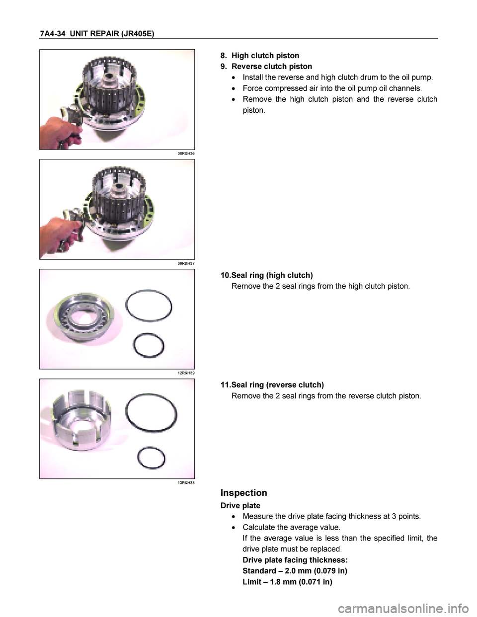
08R&H36
8. High clutch piston
9. Reverse clutch piston � Install the reverse and high clutch drum to the oil pump.
� Force compressed air into the oil pump oil channels.
� Remove the high clutch piston and the reverse clutch
piston.
09R&H37
12R&H39
10.Seal ring (high clutch)
Remove the 2 seal rings from the high clutch piston.
13R&H38
11.Seal ring (reverse clutch)
Remove the 2 seal rings from the reverse clutch piston.
Inspection
Drive plate
� Measure the drive plate facing thickness at 3 points.
� Calculate the average value.
If the average value is less than the specified limit, the
drive plate must be replaced.
Drive plate facing thickness:
Standard – 2.0 mm (0.079 in)
Limit – 1.8 mm (0.071 in)
Page 4209 of 4264
 7A4-35
Return spring � Check the number of effective return spring coils.
If the number is less than the specified minimum, the
return spring must be replaced.
Effective")
UNIT REPAIR (JR405E) 7A4-35
Return spring � Check the number of effective return spring coils.
If the number is less than the specified minimum, the
return spring must be replaced.
Effective return spring coils (standard): 10.2
� Measure the return spring outside diameter, free length,
and linear diameter.
If any of the measured values exceed the specified limit,
the return spring must be replaced.
Return spring measurements (standard):
Outside diameter – 8.0 mm (0.315 in)
Free length – 27.1 mm (1.067 in)
Linear diameter – 1.1 mm (0.043 in)
10R&H40
Reverse clutch piston
� Apply compressed air (392 kPa/4.0 kg/cm
2) to the
reverse clutch piston from the outside to the inside.
The flow of air should be blocked.
11R&H44
�
Apply compressed air (392 kPa/4.0 kg/cm2) to the
reverse clutch piston from inside to the outside.
The flow of air should be unrestricted.
12R&H39
Reassembly steps
Coat the parts with ATF before installing them.
1. Seal ring (high clutch)
Install new seal rings to the high clutch piston.
Page 4210 of 4264
7A4-36 UNIT REPAIR (JR405E)
13R&H38
2. Seal ring (reverse clutch)
Install new seal rings to the reverse clutch piston.
RTW47ASH000601
As shown in a figure, oil seal lip is attached.
14R&H32
3. Reverse clutch piston
Install the reverse clutch piston to the reverse and high
clutch drum.
15R&H31
4. High clutch piston
Install the high clutch piston to the reverse clutch piston.
16R&H33
5. Return spring
Install the return spring to the high clutch piston.
Page 4211 of 4264
UNIT REPAIR (JR405E) 7A4-37
17R&H30
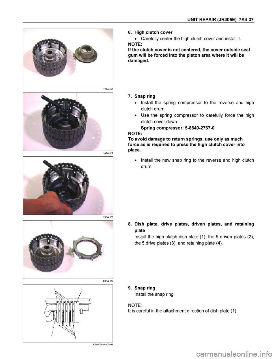
6. High clutch cover
� Carefully center the high clutch cover and install it.
NOTE:
If the clutch cover is not centered, the cover outside seal
gum will be forced into the piston area where it will be
damaged.
18R&H27
7. Snap ring
� Install the spring compressor to the reverse and high
clutch drum.
� Use the spring compressor to carefully force the high
clutch cover down.
Spring compressor: 5-8840-2767-0
NOTE:
To avoid damage to return springs, use only as much
force as is required to press the high clutch cover into
place.
19R&H28
�
Install the new snap ring to the reverse and high clutch
drum.
20R&H25
8. Dish plate, drive plates, driven plates, and retaining
plate
Install the high clutch dish plate (1), the 5 driven plates (2),
the 5 drive plates (3), and retaining plate (4).
RTW47ASH000501
9. Snap ring
Install the snap ring.
NOTE:
It is careful in the attachment direction of dish plate (1).

No. Valve
nomenclature Diameter
(mm / in) Length
(mm / in)Configuration
14 Pressure relief ---- ----
15 Pressure
regulator 16.0 /
0.630 89.5 /
3.524
16 Low a")

CLUTCH PACK (REVERSE AND
HIGH CLUTCH ASSEMBLY)
01R&H17
Legend
1. Reverse and high clutch drum
2. Seal ring (reverse clutch)
3. Lip seal (reverse clutc")
 7A4-33
03R&H21
2. Retaining plate, drive plate, driven plate and dish plate
Remove the reverse clutch retaining plate, the 2 drive
plates, the 2 driven plates, and th")

13R&H38
2. Seal ring (reverse clutch)
Install new seal rings to the reverse clutch piston.
RTW47ASH000601
As shown in a figure, oil seal lip")