Page 4233 of 4264
UNIT REPAIR (JR405E) 7A4-59
18CASE-AY43
�
Use a pin punch to drive the manual plate spring pin into
place.
21CASE-AY48
3. Detent spring
� Install the detent spring and tighten the fixing bolt to the
specified torque.
Torque: 7 N �
��
�
m (61 Ib �
��
�
in)
23CASE-AY53
4. Harness assembly
� Apply automatic transmission fluid to the new O-ring and
install them to the harness assembly.
� Install the harness assembly to the transmission case.
Tighten the fixing bolt to the specified torque.
Torque: 6 N �
��
�
m (52 Ib �
��
�
in)
24ASSY003
5. Low one-way clutch inner race
� Install new seal rings to the low one-way clutch inne
r
race.
25ASSY126
�
Measure the gap between the seal ring and the ring
groove.
If the measured valve is outside the specified range the
low one-way clutch inner race must be replaced.
Sealing ring and ring groove gap:
0.10~0.25 mm (0.0004~0.001 in)
Page 4234 of 4264
7A4-60 UNIT REPAIR (JR405E)
26L&R01
6. Low and reverse brake piston
� Install new seal rings to the low and reverse piston.
RTW47ASH000701
As shown in a figure, sealing lip is attached.
27ASSY004
�
Install the low and reverse brake piston to the
transmission case.
28ASSY005
7. Return spring
� Install the return spring to the low and reverse brake
piston.
29ASSY006
8. Low one-way clutch inner race
� Install the low one-way clutch inner race to the
transmission case.
� Temporarity tighten the 7 fixing bolts.
Page 4235 of 4264
UNIT REPAIR (JR405E) 7A4-61
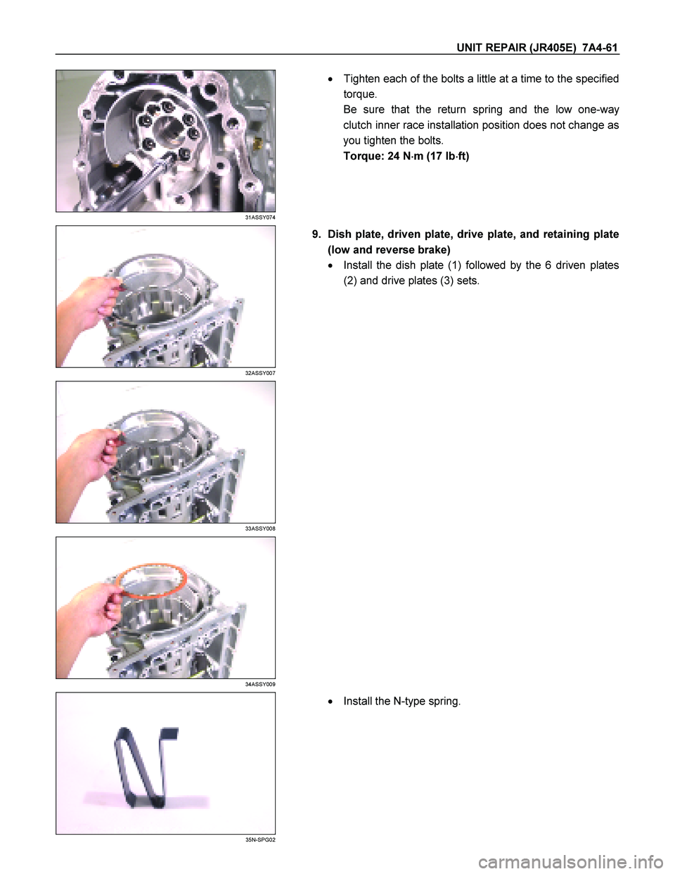
31ASSY074
�
Tighten each of the bolts a little at a time to the specified
torque.
Be sure that the return spring and the low one-way
clutch inner race installation position does not change as
you tighten the bolts.
Torque: 24 N �
��
�
m (17 Ib �
��
�
ft)
32ASSY007
9. Dish plate, driven plate, drive plate, and retaining plate
(low and reverse brake)
� Install the dish plate (1) followed by the 6 driven plates
(2) and drive plates (3) sets.
33ASSY008
34ASSY009
35N-SPG02
�
Install the N-type spring.
Page 4245 of 4264
UNIT REPAIR (JR405E) 7A4-71
Power train
01HUB-H04
Legend
1. O-ring
2. Input shaft
3. Bearing
4. Reverse and high clutch assembly
5. Bearing
6. High clutch hub
7. Bearing race
8. Bearing
9. Front sun gear
10. Bearing race
11. Bearing
12. Carrier and low clutch assembly
13. Bearing
14. Transmission case
Reassembly steps
1. Transmission case
Rotate the transmission case so that the converter housing
installation surfaces are facing up.
02ASSY012
2. Bearing
Install the bearing to the low and one-way clutch inner race.
Refer to the item “Transmission Case ” for more detailed
information.
NOTE:
Apply Vaseline to the bearing to prevent them from failing
during the installation procedure.
Page 4246 of 4264
7A4-72 UNIT REPAIR (JR405E)
03ASSY013
3. Carrier and low clutch assembly
Install the carrier and low clutch assembly to the
transmission case.
NOTE:
Do not allow the low clutch drum end to protrude beyond
the 2-4 brake plate contact surface (transmission case).
04ASSY014
4. Bearing
Install the bearing to the carrier and low clutch assembly.
05ASSY015
5. Driven plate, drive plate, retaining plate, and dish plate
(2 – 4 brake)
Install the 2-4 brake 5 driven plate (1), 5 drive plates (2),
retaining plate (3), and dish plate (4) in that order.
NOTE:
�
� �
�
The thickest driven plate (5.6 mm) must be installed
at the bottom (transmission case plate surface).
�
� �
�
Dish plate side with the identification mark must
face the retaining plate.
06ASSY016
07ASSY017
Page 4249 of 4264
UNIT REPAIR (JR405E) 7A4-75
192-4B22
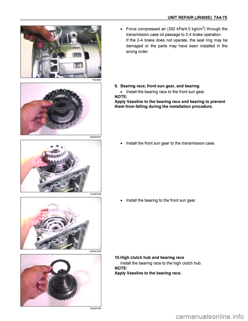
�
Force compressed air (392 kPa/4.0 kg/cm2) through the
transmission case oil passage to 2-4 brake operation.
If the 2-4 brake does not operate, the seal ring may be
damaged or the parts may have been installed in the
wrong order.
20ASSY037
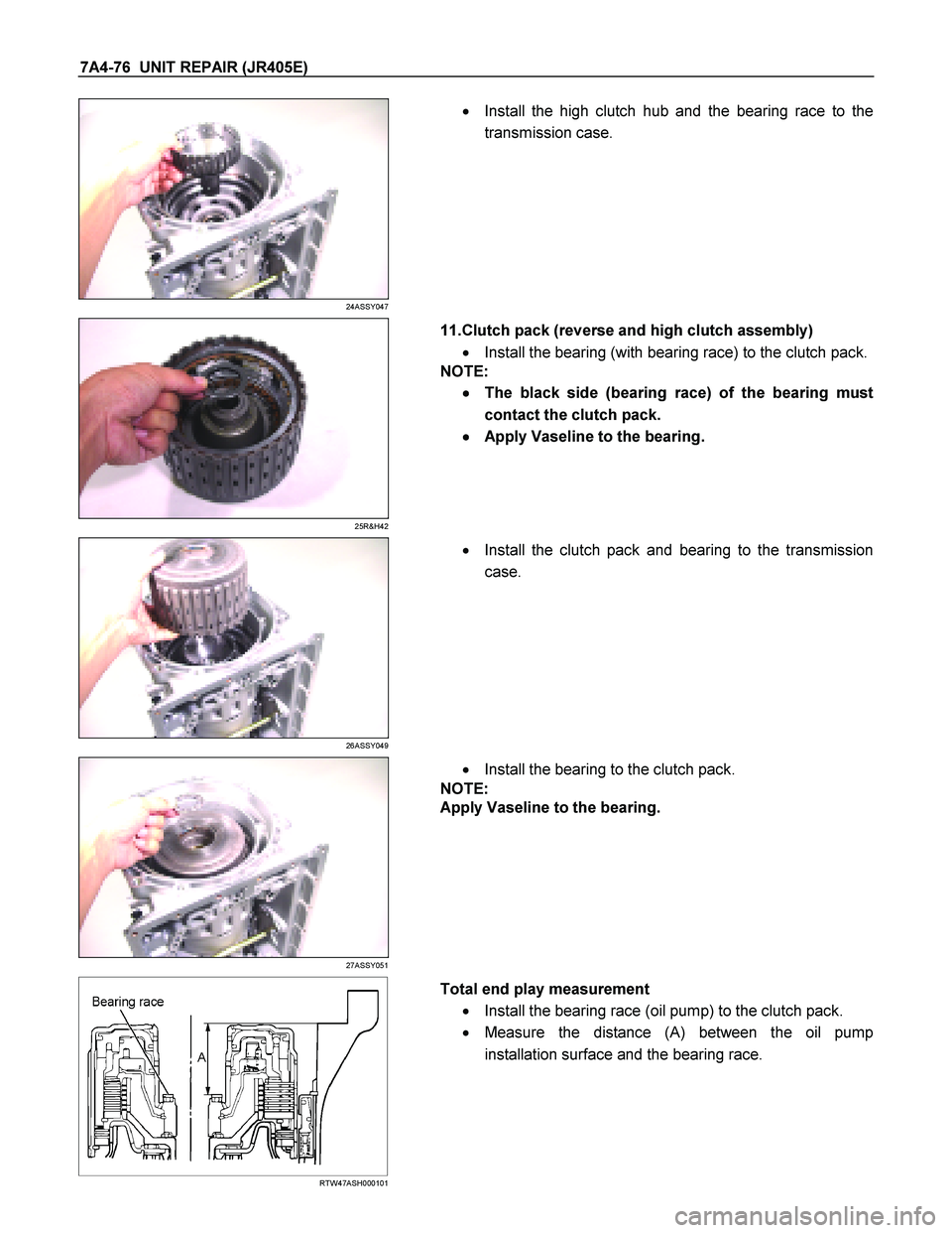
9. Bearing race, front sun gear, and bearing
� Install the bearing race to the front sun gear.
NOTE:
Apply Vaseline to the bearing race and bearing to prevent
them from falling during the installation procedure.
21ASSY040
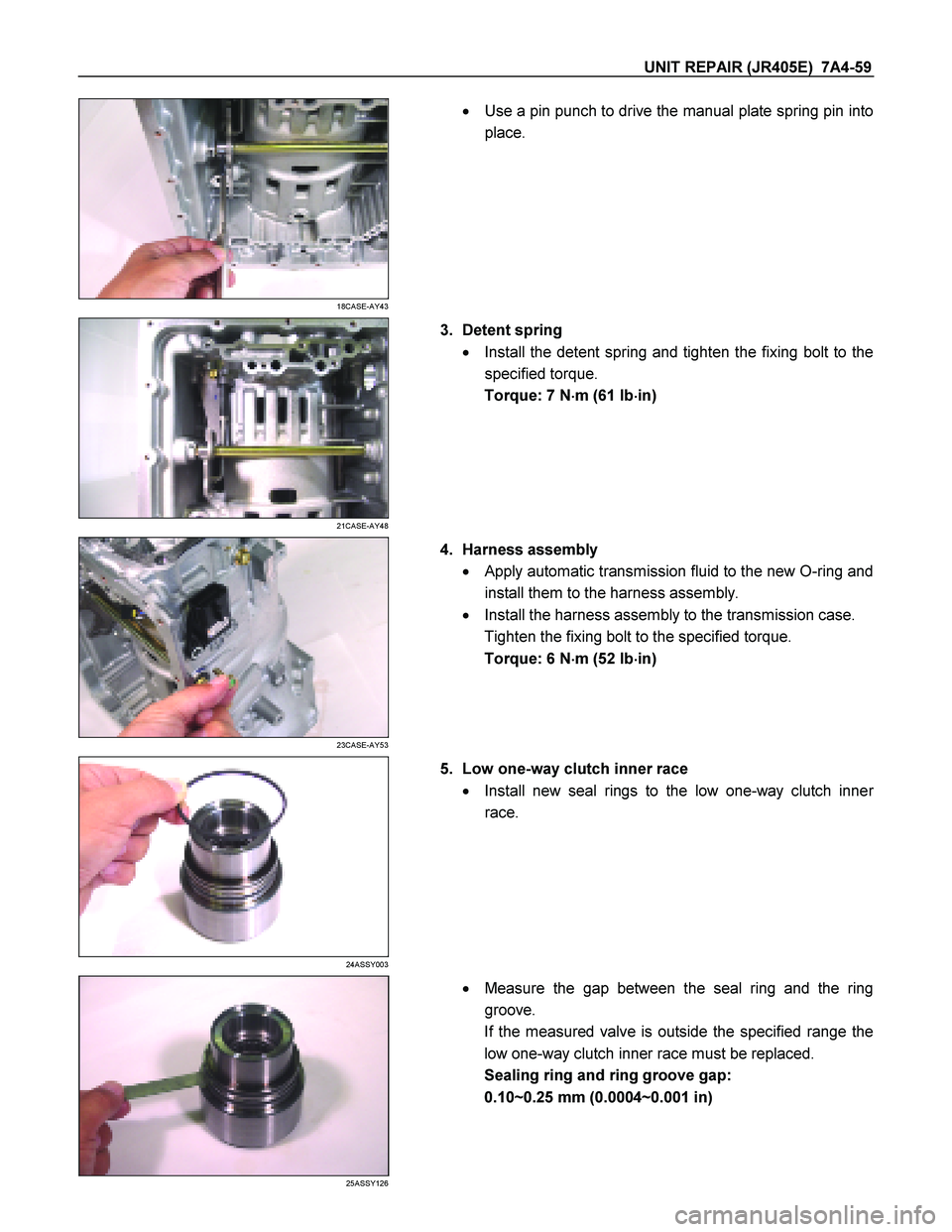
� Install the front sun gear to the transmission case.
22ASSY042
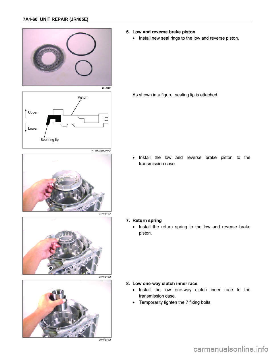
� Install the bearing to the front sun gear.
23ASSY045
10.High clutch hub and bearing race
Install the bearing race to the high clutch hub.
NOTE:
Apply Vaseline to the bearing race.
Page 4250 of 4264
7A4-76 UNIT REPAIR (JR405E)
24ASSY047
�
Install the high clutch hub and the bearing race to the
transmission case.
25R&H42
11.Clutch pack (reverse and high clutch assembly)
� Install the bearing (with bearing race) to the clutch pack.
NOTE:
�
� �
�
The black side (bearing race) of the bearing must
contact the clutch pack.
�
� �
�
Apply Vaseline to the bearing.
26ASSY049
�
Install the clutch pack and bearing to the transmission
case.
27ASSY051
�
Install the bearing to the clutch pack.
NOTE:
Apply Vaseline to the bearing.
RTW47ASH000101
Total end play measurement
� Install the bearing race (oil pump) to the clutch pack.
� Measure the distance (A) between the oil pump
installation surface and the bearing race.
Page 4257 of 4264
 7A4-83
Torque: 5.5 N�
�� �m (48 Ib�
�� �in)
� Remove the holding fixture from the transmission case.
RTW47ASH001001
23.Speed sensor and turbine sensor
� Apply ATF")
UNIT REPAIR (JR405E) 7A4-83
Torque: 5.5 N�
�� �m (48 Ib�
�� �in)
� Remove the holding fixture from the transmission case.
RTW47ASH001001
23.Speed sensor and turbine sensor
� Apply ATF to the new O-rings and install them the speed
sensor (2) and the turbine sensor (3).
� Install the speed sensor and the turbine sensor. Tighten
the bolt to the specified torque.
Torque: 6 N�
�� �m (52 Ib�
�� �in)
24.Torque converter
� Pour the new ATF into the torque converter.
� Shake the torque converter to thoroughly clean the
inside.
� Drain the ATF from the torque converter.
� Pour the new ATF into the torque converter.
NOTE:
If significant amounts of foreign material (clutch facing,
metallic fragments, etc.) are found in the automatic
transmission at time of disassembly, the existing torque
converter must be replaced with a new one.
RTW47ASH000901
� Install the torque converter.
� Measure the torque converter end play (A).
If the measured value is greater than the specified
minimum, the torque converter is correctly installed.
Torque converter end pay (Minimum): 67 mm (2.64
in)
 7A4-71
Power train
01HUB-H04
Legend
1. O-ring
2. Input shaft
3. Bearing
4. Reverse and high clutch assembly
5. Bearing
6. High clutch hub
7. Bearing race")

03ASSY013
3. Carrier and low clutch assembly
Install the carrier and low clutch assembly to the
transmission case.
NOTE:
Do not allow the low clutch drum")