Page 4183 of 4264
UNIT REPAIR (JR405E) 7A4-9
29ASSY091
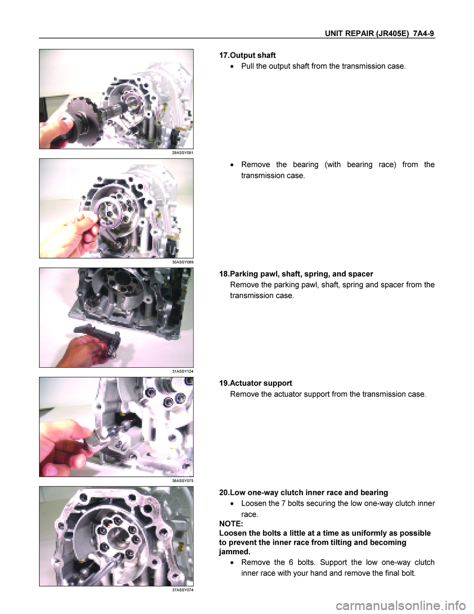
17.Output shaft
� Pull the output shaft from the transmission case.
30ASSY089
�
Remove the bearing (with bearing race) from the
transmission case.
31ASSY124
18.Parking pawl, shaft, spring, and spacer
Remove the parking pawl, shaft, spring and spacer from the
transmission case.
36ASSY075
19.Actuator support
Remove the actuator support from the transmission case.
37ASSY074
20.Low one-way clutch inner race and bearing
� Loosen the 7 bolts securing the low one-way clutch inne
r
race.
NOTE:
Loosen the bolts a little at a time as uniformly as possible
to prevent the inner race from tilting and becoming
jammed.
� Remove the 6 bolts. Support the low one-way clutch
inner race with your hand and remove the final bolt.
Page 4184 of 4264
7A4-10 UNIT REPAIR (JR405E)
39ASSY006
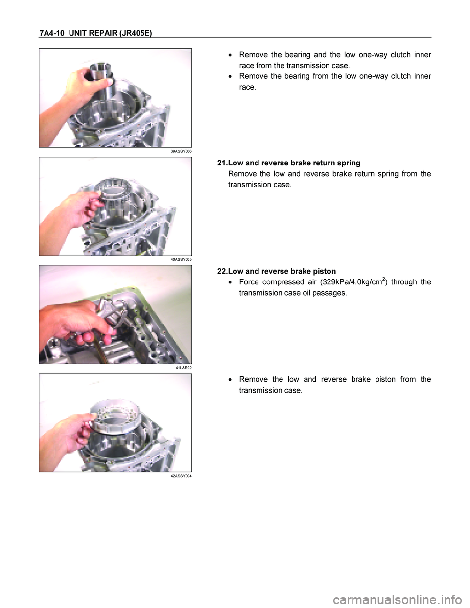
�
Remove the bearing and the low one-way clutch inner
race from the transmission case.
� Remove the bearing from the low one-way clutch inne
r
race.
40ASSY005
21.Low and reverse brake return spring
Remove the low and reverse brake return spring from the
transmission case.
41L&R02
22.Low and reverse brake piston
� Force compressed air (329kPa/4.0kg/cm
2) through the
transmission case oil passages.
42ASSY004
�
Remove the low and reverse brake piston from the
transmission case.
Page 4189 of 4264
UNIT REPAIR (JR405E) 7A4-15
244L300003
Legend
1. High clutch oil pressure switch connector
(wire color: Gray)
2. 2-4 brake oil pressure switch connector
(wire color: Brown)
3. Low and reverse brake oil pressure
switch connector (wire color: White)
4. Low and reverse brake duty solenoid
connector (wire color: Pink and White)
5. High clutch duty solenoid connector
(wire color: Green and Gray)
6. Lock-up duty solenoid connector (wire
color: Yellow and Black)
7. 2-4 brake duty solenoid connector (wire
color: Blue and Brown)
8. Low clutch duty solenoid connector (wire
color: Orange and Black)
9. Line pressure solenoid connector (wire
color: Pink)
Page 4190 of 4264
7A4-16 UNIT REPAIR (JR405E)
12CV19
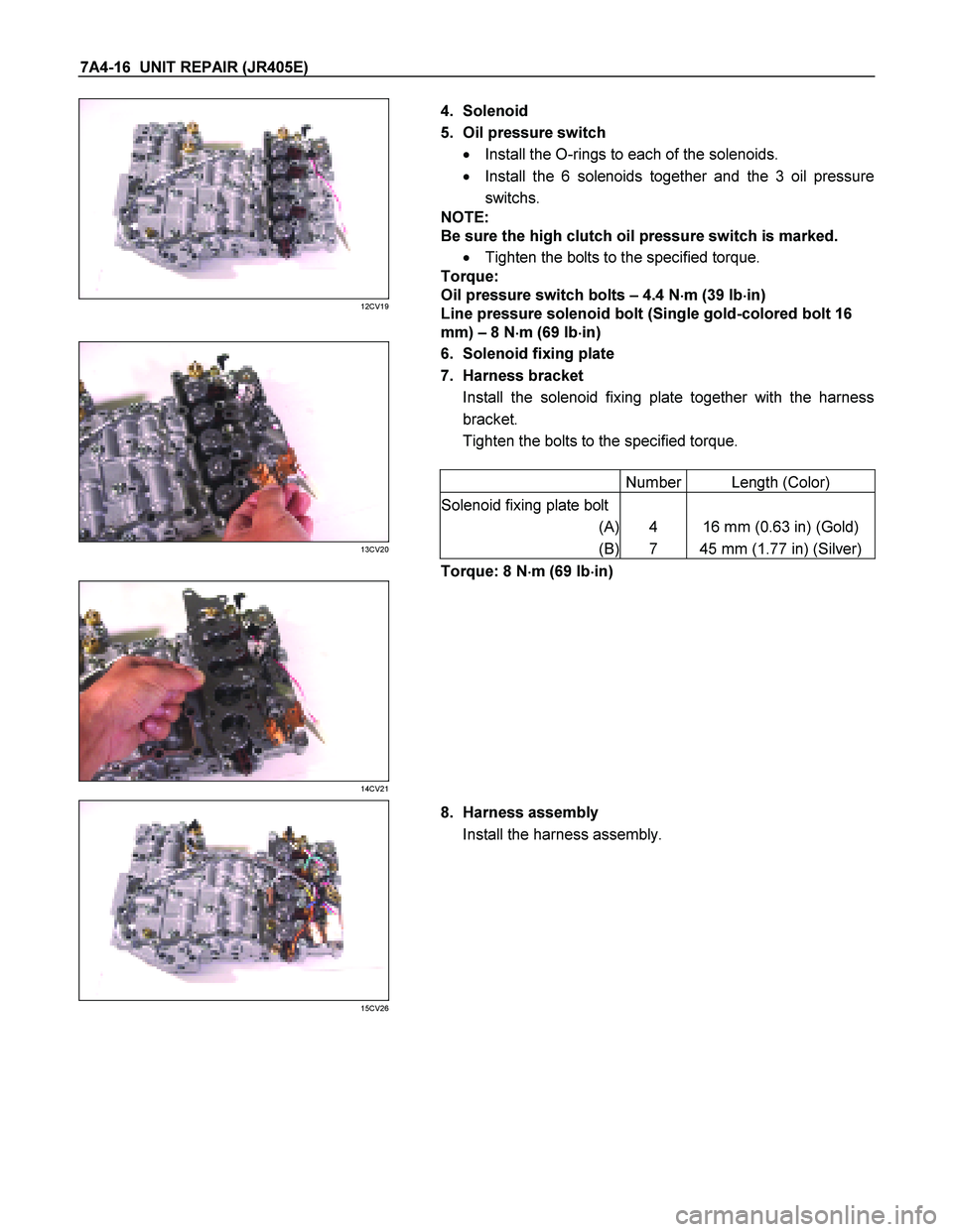
4. Solenoid
5. Oil pressure switch � Install the O-rings to each of the solenoids.
� Install the 6 solenoids together and the 3 oil pressure
switchs.
NOTE:
Be sure the high clutch oil pressure switch is marked.
� Tighten the bolts to the specified torque.
Torque:
Oil pressure switch bolts – 4.4 N �
��
�
m (39 Ib �
��
�
in)
Line pressure solenoid bolt (Single gold-colored bolt 16
mm) – 8 N �
��
�
m (69 Ib �
��
�
in)
6. Solenoid fixing plate
7. Harness bracket Install the solenoid fixing plate together with the harness
bracket.
Tighten the bolts to the specified torque.
Number Length (Color)
Solenoid fixing plate bolt
(A) 4 16 mm (0.63 in) (Gold)
(B) 7 45 mm (1.77 in) (Silver)
13CV20
Torque: 8 N �
��
�
m (69 Ib �
��
�
in)
14CV21
15CV26
8. Harness assembly
Install the harness assembly.
Page 4192 of 4264
7A4-18 UNIT REPAIR (JR405E)
CONTROL VALVE UPPER BODY
09CV02
Legend
1. Manual valve, and pin
2. Retainer plate, spring, and 2-4 brake
accumulator
3. Retainer plate, plug, and low and
reverse brake fail valve B
4. Retainer plate, plug, spring, and reverse
stall valve
5. Retainer plate, spring, and low and
reverse brake solenoid accumulator
6. Retainer plate, spring, and pilot valve
7. Retainer plate, spring, and low clutch
solenoid accumulator
8. Retainer plate, plug, spring, and low
clutch amp valve A
9. Retainer plate, plug, spring, and 2-4
brake fail valve B
10. Retainer plate, sleeve, plug, spring, and
lock-up control valve
11. Retainer plate, plug, spring, and 2-4
brake amp valve
12. Retainer plate, plug, spring, and high
clutch amp valve
13. Retainer plate, spring, and high clutch
solenoid accumulator
14. Control valve upper body
15. Spring
16. Steel ball
Page 4195 of 4264
UNIT REPAIR (JR405E) 7A4-21
No. Valve
nomenclature Diameter
(mm / in) Length
(mm / in)Configuration
1 Manual 12.0 /
0.472 82.0 /
3.228
2 2 – 4 brake
accumulator 15.0 /
0.591 37.5 /
1.476
3 Low and reverse
brake fail (B) 10.0 /
0.394 52.0 /
2.047
4 Reverse stall 8.0 /
0.315 50.0 /
1.969
5 Low and reverse
brake solenoid
accumulator 14.0 /
0.551 19.5 /
0.768
6 Pilot 12.0 /
0.472 38.5 /
1.516
7 Low clutch
solenoid
accumulator 14.0 /
0.551 19.5 /
0.768
8 Low clutch amp
(A) 12.0 /
0.472 53.5 /
2.106
9 2 – 4 brake fail
(B) 10.0 /
0.394 39.0 /
1.535
10 Lock-up control 12.9 /
0.508 57.5 /
2.264
11 2 – 4 brake amp 12.0 /
0.472 53.5 /
2.106
Page 4196 of 4264

12 High clutch amp 12.0 /
0.472 53.5 /
2.106
13 High clutch
solenoid
accumulator 14.0 /
0.551 19.5 /
0.768
Spring specifications
No. Valve nomenclature Free")
7A4-22 UNIT REPAIR (JR405E)
12 High clutch amp 12.0 /
0.472 53.5 /
2.106
13 High clutch
solenoid
accumulator 14.0 /
0.551 19.5 /
0.768
Spring specifications
No. Valve nomenclature Free length
(mm / in) Outside
diameter (mm
/ in) Linear
diameter (mm
/ in) Number of
coils
1 Manual ---- ---- ---- ----
2 2 – 4 brake accumulator 43.9 / 1.728 11.0 / 0.433 2.0 / 0.079 13.1
3 Low and reverse brake fail (B) 22.0 / 0.866 7.0 / 0.276 0.6 / 0.024 10.0
4 Reverse stall 31.5 / 1.240 7.0 / 0.276 1.0 / 0.039 12.8
5 Low and reverse solenoid brake
accumulator 31.4 / 1.236 9.8 / 0.386 1.3 / 0.051 9.3
6 Pilot 32.0 / 1.260 11.0 / 0.433 1.3 / 0.051 9.2
7 Low clutch solenoid accumulator 31.4 / 1.236 9.8 / 0.386 1.3 / 0.051 9.3
8 Low clutch amp (A) 23.0 / 0.906 11.0 / 0.433 0.5 / 0.020 13.2
9 2 – 4 brake fail (B) 24.8 / 0.976 8.5 / 0.335 0.9 / 0.035 7.8
10 Lock-up control 27.0 / 1.063 14.0 / 0.551 1.1 / 0.043 5.7
11 2 – 4 brake amp 23.0 / 0.906 11.0 / 0.433 0.5 / 0.020 13.2
12 High clutch amp 23.0 / 0.906 11.0 / 0.433 0.5 / 0.020 13.2
13 High clutch solenoid accumulator 31.4 / 1.236 9.8 / 0.386 1.3 / 0.051 9.3
Reassembly steps
� Coat the parts with ATF before installing them.
� Install the control valve to the upper body.
� Install the 11 steel balls and spring to the upper body.
Page 4197 of 4264
UNIT REPAIR (JR405E) 7A4-23
CONTROL VALVE LOWER BODY
10CV11
Legend
1. Retainer plate, spring, and steel ball
2. Retainer plate, plug, spring, and
pressure regulator valve
3. Retainer plate, spring, and high clutch
accumulator
4. Retainer plate, plug, low and reverse
brake fail valve A, and spring
5. Retainer plate, plug, spring, and fail
valve
6. Retainer plate, plug, low and reverse
brake amp valve, and spring
7. Oil pressure switch
8. Oil filter
9. Solenoid
10. Line pressure solenoid
11. Lock-up solenoid
12. Harness bracket
13. Solenoid fixing plate
14. Harness assembly
15. Retainer plate, plug, spring, and 2-4
brake fail valve A
16. Retainer plate, plug, spring, and low
clutch amp valve B
17. Retainer plate, spring, and torque
converter relief valve
18. Oil strainer
19. Control valve lower body
20. Retainer plate, spring, and 2-4 brake
solenoid accumulator
21. Oil pressure switch
 7A4-15
244L300003
Legend
1. High clutch oil pressure switch connector
(wire color: Gray)
2. 2-4 brake oil pressure switch connector
(wire color: Brown)
3. Low and r")

CONTROL VALVE UPPER BODY
09CV02
Legend
1. Manual valve, and pin
2. Retainer plate, spring, and 2-4 brake
accumulator
3. Retainer plate, plug, and low an")
 7A4-21
No. Valve
nomenclature Diameter
(mm / in) Length
(mm / in)Configuration
1 Manual 12.0 /
0.472 82.0 /
3.228
2 2 – 4 brake
accumulator 15.0 /
0.591 37.5 /
1.476")
 7A4-23
CONTROL VALVE LOWER BODY
10CV11
Legend
1. Retainer plate, spring, and steel ball
2. Retainer plate, plug, spring, and
pressure regulator valve
3. Retain")