Page 4169 of 4264
 7A3-17
Remove or Disconnect
1. Block the wheels.
2. Disconnect the negative battery cable.
3. Drain the fluid.
Refer to “ATF CHANGE” in this section.
4. Rem")
ON-VEHICLE SERVICE (JR405E) 7A3-17
Remove or Disconnect
1. Block the wheels.
2. Disconnect the negative battery cable.
3. Drain the fluid.
Refer to “ATF CHANGE” in this section.
4. Remove the 19 bolts and oil pan.
5. Inspect the bottom of the oil pan and strainer netting
for foreign material (clutch facing and metal
shavings).
If there is an excessive accumulation of foreign
material, the oil strainer must be replaced.
Further inspection is required to determine the
source of the foreign material.
6. Remove the harness assembly (including oil
temperature sensor).
7. Remove the 11 bolts and the solenoid fixing plate.
8. Remove the 6 solenoids and 3 oil pressure switchs.
Inspect
Oil pressure switch
Apply compressed air (392 kPa/4.0 kg/cm2) to the oil
pressure switch to check the oil pressure switch
continuity between the connector and screw.
Oil temperature sensor (harness assembly)
Check the oil temperature sensor resistance between
harness terminals 7 and 6 (ground).
Oil temperature sensor resistance:
2,400~2,600 ohms (20�
�� �C)
244L300011
Solenoid
Measure the resistance of each solenoid.
Resistance:
Brown connector – 3.0~3.4 ohms (20�
�� �C)
Gray connector – 12.0~13.2 ohms (20�
�� �C)
White connector – 12.2~13.4 ohms (20�
�� �C)
Install or connect
1. Install the O-rings to each of the solenoids.
2. Install the 6 solenoids and 3 oil pressure switchs.
Line pressure solenoid bolt torque:
8 N·m (69 lb·in)
Oil pressure switch bolt torque:
4.4 N·m (39 lb·in)
3. Install the solenoid fixing plate together with the
harness brackets.
Number Length (Color)
Solenoid fixing plate bolt
(A)
(B)
4
7
16 mm (0.63 in) (Gold)
45 mm (1.77 in) (Silver)
Bolt torque : 8 N·m (69 lb·in)
4. Install the harness assembly.
5. If removed, install the oil strainer.
Number Length (Color)
Oil strainer bolt
(C)
(D)
9
4
13 mm (0.51 in) (Silver)
45 mm (1.77 in) (Silver)
Bolt torque : 8 N·m (69 lb·in)
6. Install the new gasket and oil pan.
Bolt torque : 8 N·m (69 lb·in)
7. Fill the fluid.
Refer to “ATF CHANGE” in this section.
8. Connect the negative battery cable.
9. Remove the wheel blocks.
Page 4170 of 4264
7A3-18 ON-VEHICLE SERVICE (JR405E)
CONTROL VALVE ASSEMBLY
244L300001
Remove or Disconnect
1. Block the wheels.
2. Disconnect the negative battery cable.
3. Drain the fluid.
Refer to “ATF CHANGE” in this section.
4. Remove the 19 bolts and oil pan.
5. Inspect the bottom of the oil pan and strainer netting
for foreign material (clutch facing and metal
shavings).
If there is an excessive accumulation of foreign
material, the oil strainer must be replaced.
Further inspection is required to determine the
source of the foreign material.
6. Disconnect the 2 harness connectors leading to the
control valve.
7. Remove the 12 bolts and the control valve assembly.
Number of bolts Length
10 (A)
2 (B) 40 mm (1.57 in)
30 mm (1.18 in)
Note:
Take care not to disturb the manual valve (inside the
control valve assembly).
Do not allow the pin to fall free (the pin prevents the
valve from turning).
Page 4171 of 4264
 7A3-19
Install or Connect
1. Align the manual valve and the manual plate of the
transmission case.
43ASSY119
2. Install the control valve assembly and tighten the 12")
ON-VEHICLE SERVICE (JR405E) 7A3-19
Install or Connect
1. Align the manual valve and the manual plate of the
transmission case.
43ASSY119
2. Install the control valve assembly and tighten the 12
fixing bolts to the specified torque.
Number of bolts Length Color
10 (A) 40 mm (1.57 in) Gold
2 (B) 30 mm (1.18 in) Gold
Bolt torque : 8 N·m (69 lb·in)
3. Connect the 2 harness connectors.
4. If removed, install the oil strainer.
Refer to “Solenoids, Oil Pressure Switch and Oil
Temperature Sensor” previously in this section.
5. Install the new gasket and oil pan.
Bolt torque : 8 N·m (69 lb·in)
6. Fill the fluid.
Refer to “ATF CHANGE” in this section.
7. Connect the negative battery cable.
8. Remove the wheel blocks.
FLUSHING THE TRANSMISSION FLUID COOLER AND LINE
The fluid cooler and lines may be flushed under the
following condition. This will help prevent more trouble
after the transmission is repaired.
1. When the abnormal amount of debris are found.
2. When the abnormal wear or chips on gears and
shafts are found while overhauling.
3. When the abnormal clutch facing wear and oil
contamination are found.
Procedures
1. Block the wheels.
2. Disconnect negative battery cable.
3. Raise vehicle and support with suitable safety
stands.
4. Disconnect fluid cooler lines at transmission case
and fluid cooler.
5. Flush and back-flush the fluid cooler and lines using
solvent and compressed air.
Note:
DO NOT exceed 197 kPa (29 psi) air pressure or
damage may result to oil cooler.
6. Remove all remaining solvent from the system with
compressed air.
7. Flush the cooling system again with Automatic
Transmission Fluid (ATF).
After the final flush, connect all lines.
Cooler line joint connector torque :
44 N·m (33 lb·ft)
8. Replenish ATF
9. Start engine to test the system for the free flow o
f
fluid. If the flow is restricted, the cooler assembly o
r
lines must be replaced.
Repeated cleaning and flushing may not remove all
debris from the fluid cooler circuit.
Move the select lever through the various ranges and
return to neutral.
Check for fluid level.
If the fluid level is below the specified range, ATF
must be added.
10. Connect negative battery cable.
11. Remove safety stands.
12. Remove wheel blocks.
Page 4175 of 4264
 7A4-1
SECTION 7A4
UNIT REPAIR (JR405E)
TABLE OF CONTENTS
PAGE
Automatic Transmission Disassembly ..................................................................... 7A4")
UNIT REPAIR (JR405E) 7A4-1
SECTION 7A4
UNIT REPAIR (JR405E)
TABLE OF CONTENTS
PAGE
Automatic Transmission Disassembly ..................................................................... 7A4 - 2
Control Valve Assembly ............................................................................................ 7A4 - 11
Control Valve Upper Body ........................................................................................ 7A4 - 18
Control Valve Lower Body ........................................................................................ 7A4 - 23
Oil Pump Assembly ................................................................................................... 7A4 - 28
Clutch Pack (Reverse and High Clutch Assembly) ................................................. 7A4 - 33
Carrier and Low Clutch Assembly ........................................................................... 7A4 - 41
Transmission Case .................................................................................................... 7A4 - 54
Bearing and Bearing Race Installation Position ..................................................... 7A4 - 66
Automatic Transmission Reassembly ..................................................................... 7A4 - 69
Service Standard ....................................................................................................... 7A4 - 83
Special Service Tool .................................................................................................. 7A4 - 85
Page 4178 of 4264
7A4-4 UNIT REPAIR (JR405E)
04CV37
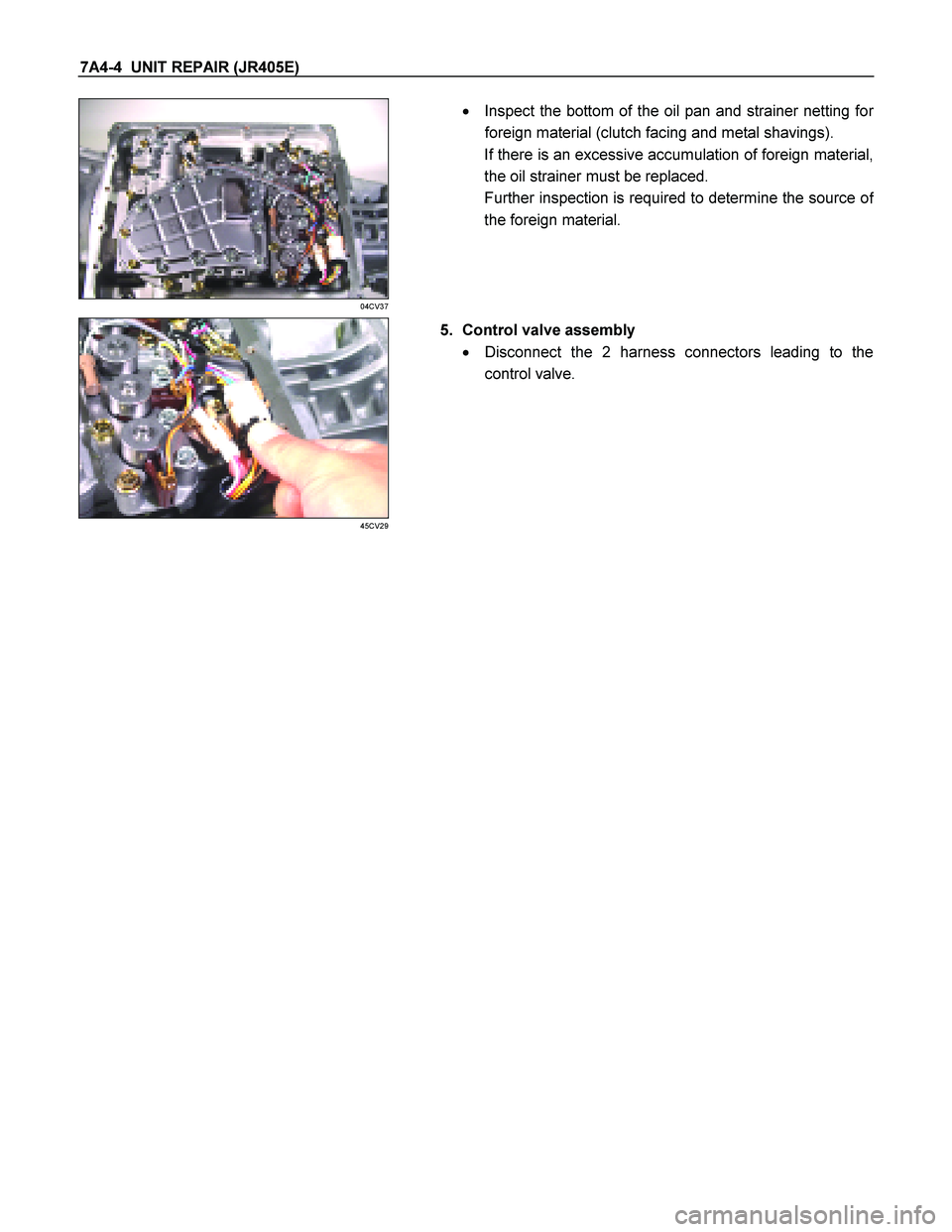
�
Inspect the bottom of the oil pan and strainer netting for
foreign material (clutch facing and metal shavings).
If there is an excessive accumulation of foreign material,
the oil strainer must be replaced.
Further inspection is required to determine the source o
f
the foreign material.
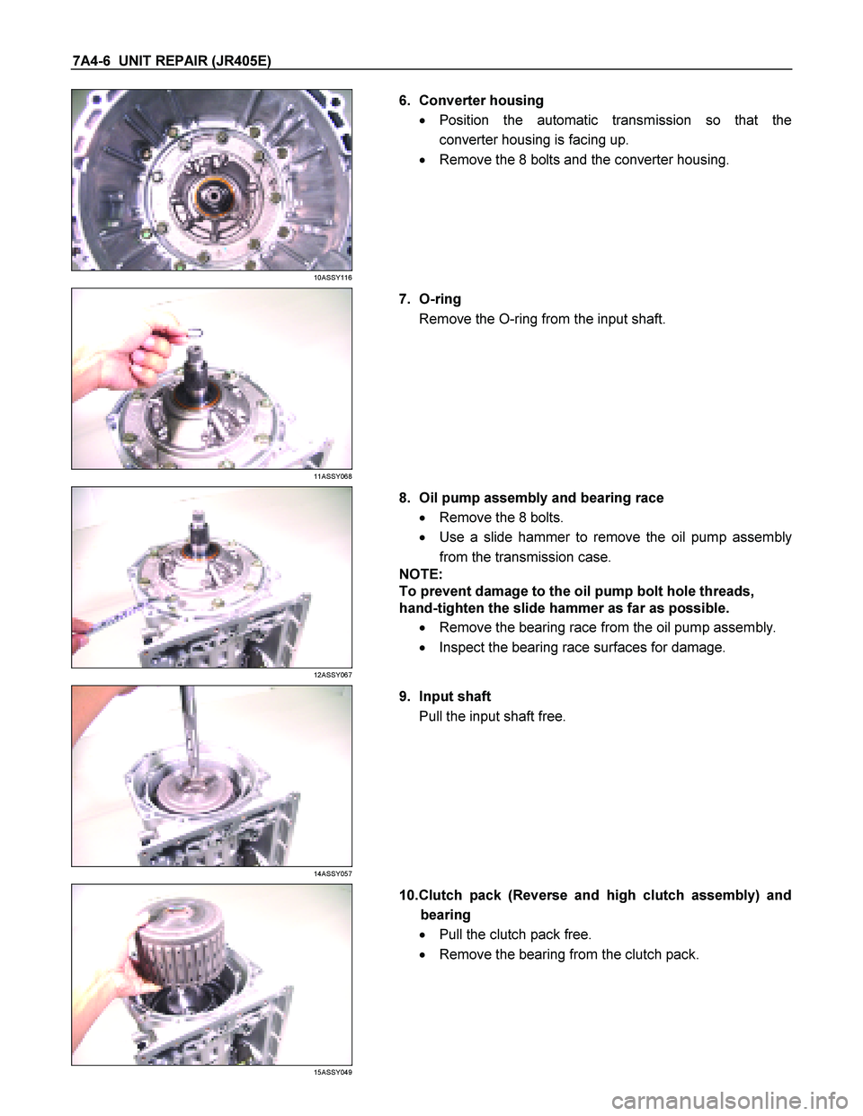
45CV29
5. Control valve assembly
� Disconnect the 2 harness connectors leading to the
control valve.
Page 4180 of 4264
7A4-6 UNIT REPAIR (JR405E)
10ASSY116
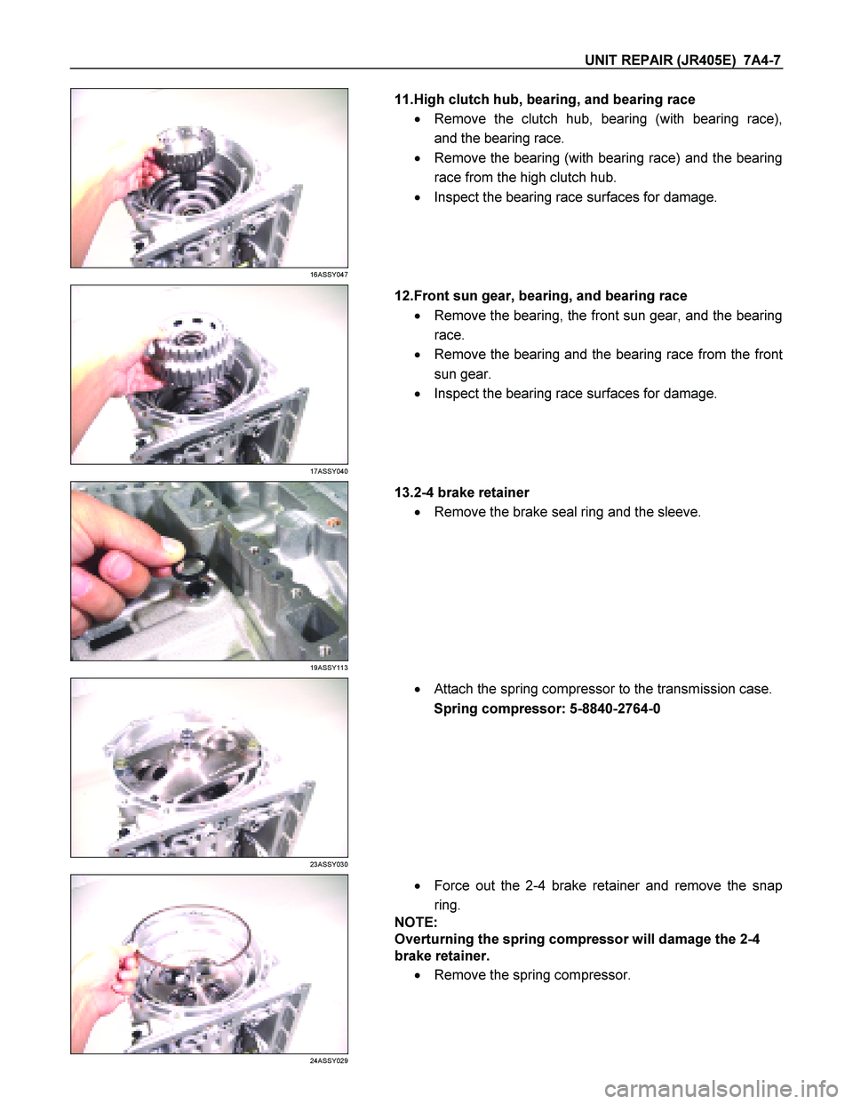
6. Converter housing
� Position the automatic transmission so that the
converter housing is facing up.
� Remove the 8 bolts and the converter housing.
11ASSY068
7. O-ring
Remove the O-ring from the input shaft.
12ASSY067
8. Oil pump assembly and bearing race
� Remove the 8 bolts.
� Use a slide hammer to remove the oil pump assembly
from the transmission case.
NOTE:
To prevent damage to the oil pump bolt hole threads,
hand-tighten the slide hammer as far as possible.
� Remove the bearing race from the oil pump assembly.
� Inspect the bearing race surfaces for damage.
14ASSY057
9. Input shaft
Pull the input shaft free.
15ASSY049
10.Clutch pack (Reverse and high clutch assembly) and
bearing
� Pull the clutch pack free.
� Remove the bearing from the clutch pack.
Page 4181 of 4264
UNIT REPAIR (JR405E) 7A4-7
16ASSY047
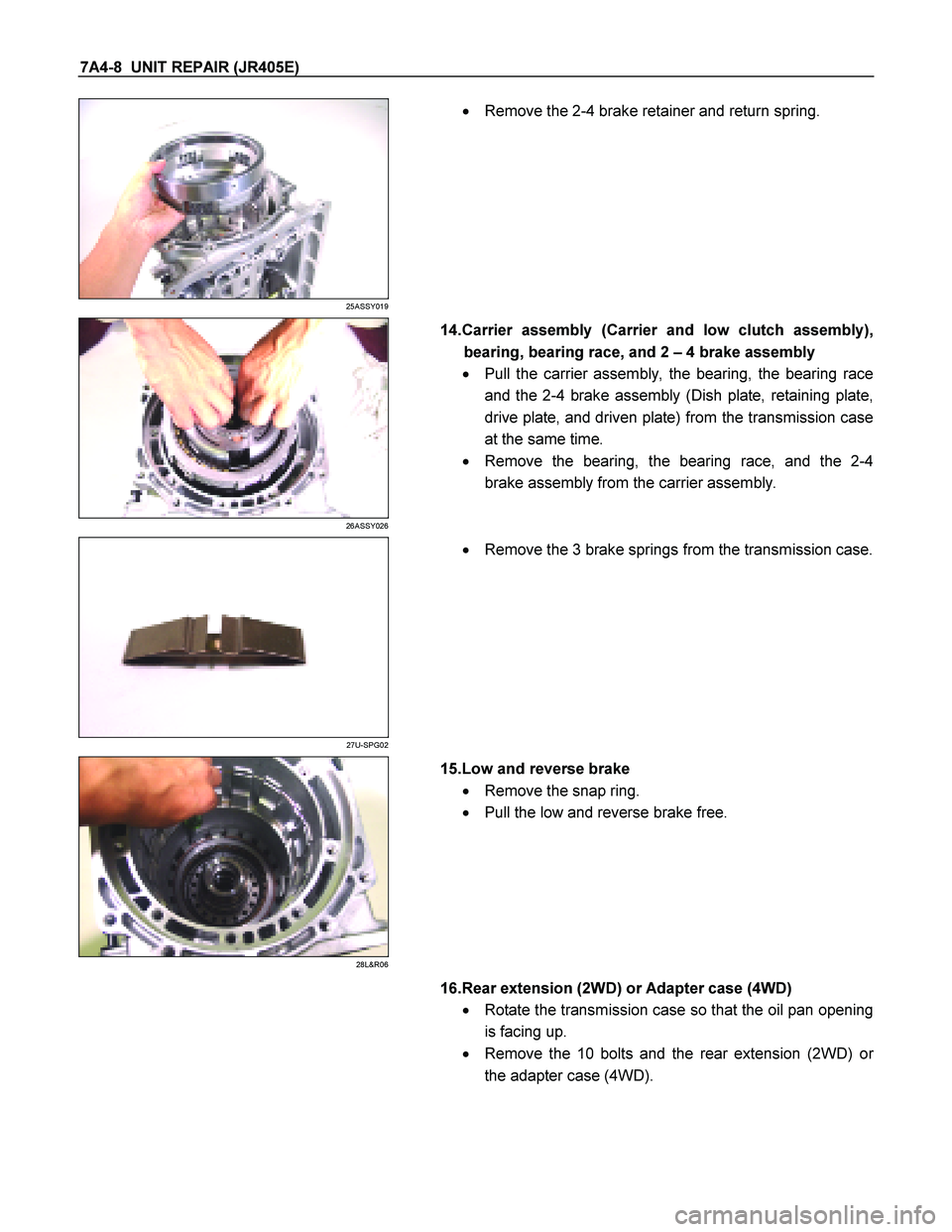
11.High clutch hub, bearing, and bearing race
� Remove the clutch hub, bearing (with bearing race),
and the bearing race.
� Remove the bearing (with bearing race) and the bearing
race from the high clutch hub.
� Inspect the bearing race surfaces for damage.
17ASSY040
12.Front sun gear, bearing, and bearing race
� Remove the bearing, the front sun gear, and the bearing
race.
� Remove the bearing and the bearing race from the fron
t
sun gear.
� Inspect the bearing race surfaces for damage.
19ASSY113
13.2-4 brake retainer
� Remove the brake seal ring and the sleeve.
23ASSY030
�
Attach the spring compressor to the transmission case.
Spring compressor: 5-8840-2764-0
24ASSY029
�
Force out the 2-4 brake retainer and remove the snap
ring.
NOTE:
Overturning the spring compressor will damage the 2-4
brake retainer.
� Remove the spring compressor.
Page 4182 of 4264
7A4-8 UNIT REPAIR (JR405E)
25ASSY019
�
Remove the 2-4 brake retainer and return spring.
26ASSY026
14.Carrier assembly (Carrier and low clutch assembly),
bearing, bearing race, and 2 – 4 brake assembly
� Pull the carrier assembly, the bearing, the bearing race
and the 2-4 brake assembly (Dish plate, retaining plate,
drive plate, and driven plate) from the transmission case
at the same time.
� Remove the bearing, the bearing race, and the 2-4
brake assembly from the carrier assembly.
27U-SPG02
�
Remove the 3 brake springs from the transmission case.
28L&R06
15.Low and reverse brake
� Remove the snap ring.
� Pull the low and reverse brake free.
16.Rear extension (2WD) or Adapter case (4WD)
� Rotate the transmission case so that the oil pan opening
is facing up.
� Remove the 10 bolts and the rear extension (2WD) o
r
the adapter case (4WD).

CONTROL VALVE ASSEMBLY
244L300001
Remove or Disconnect
1. Block the wheels.
2. Disconnect the negative battery cable.
3. Drain the fluid.
Refer to “AT")