Page 3420 of 4264
3A-4 FRONT ALIGNMENT
Alignment for 4�
�� �
2 (Except High Ride Suspension)
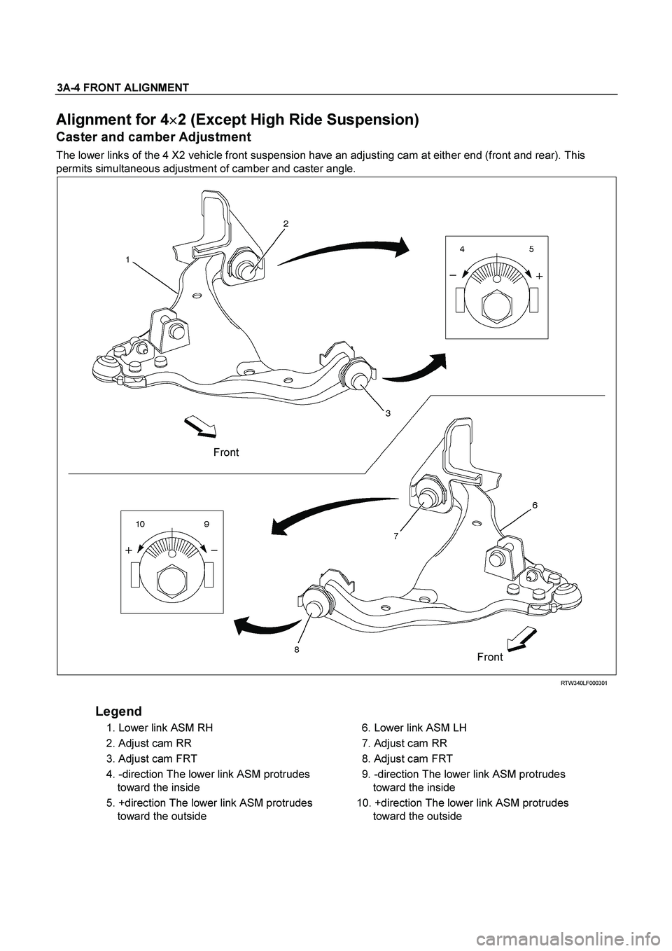
Caster and camber Adjustment
The lower links of the 4 X2 vehicle front suspension have an adjusting cam at either end (front and rear). This
permits simultaneous adjustment of camber and caster angle.
Front
Front
RTW340LF000301
Legend
1. Lower link ASM RH
2. Adjust cam RR
3. Adjust cam FRT
4. -direction The lower link ASM protrudes
toward the inside
5. +direction The lower link ASM protrudes
toward the outside
6. Lower link ASM LH
7. Adjust cam RR
8. Adjust cam FRT
9. -direction The lower link ASM protrudes
toward the inside
10. +direction The lower link ASM protrudes
toward the outside
Page 3424 of 4264

3A-8 FRONT ALIGNMENT
Toe-in Adjustment
Measurement should be taken with the vehicle on a surface
plate.
If a surface plate is not available, toe-in should be checked
with the vehicle parked on a level floor.
1. Set front wheels to straight ahead position.
2. Align the toe-in gauge with center height of each wheel a
t
front end.
3.
Apply center marks to each wheel, then take measurement
of distance A between the center marks on each wheel.
4. Slowly move the vehicle rearward until the center marks
reach the rear end position.
5. Take measurement of distance B between the cente
r
marks at rear end.
The toe-in can be calculated with next formula.
Toe-in = B - A
Toe-in mm (in)
4�
2
(Except high ride suspension) 0�
2 (0�
0.08)
To adjust the toe-in angle, loosen the lock nuts (2) on the tie
rod (1) and turn the tie rod. Turn both rods the same amount,
to keep the steering wheel centered.
Lock Nut Torque N�
m (kgf�
m/lb�
ft)
98�6.0 (10.0�0.6 / 72.3�4.3)
RTW330SH000101
Trim Height
Trim Height : at Curb Weight (Reference Data)
Trim height (Z) = A - B
Front mm (in)
Z
105(4.13)
Page 3425 of 4264
FRONT ALIGNMENT 3A-9
RTW340SH001301-X
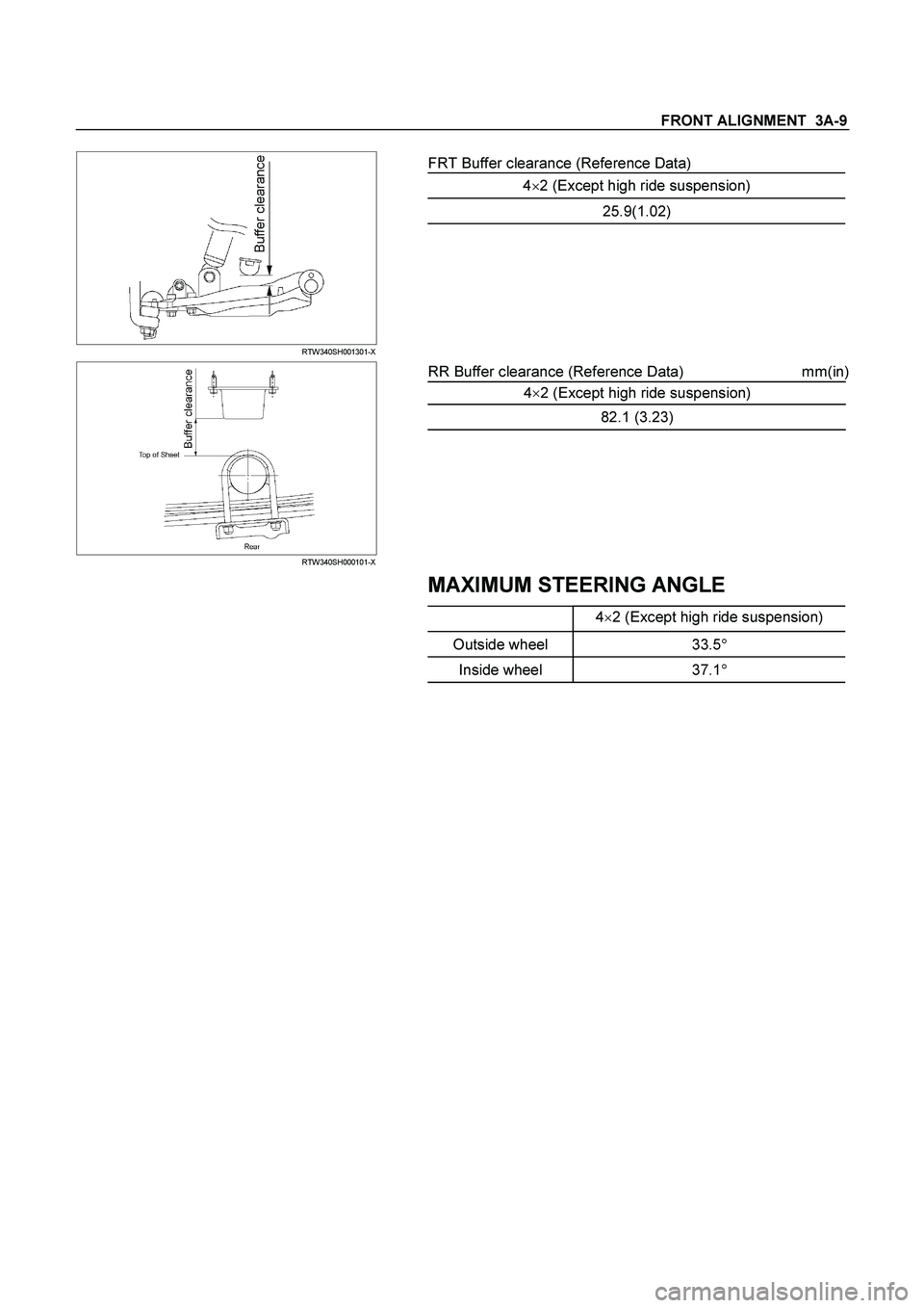
FRT Buffer clearance (Reference Data)
4�2 (Except high ride suspension)
25.9(1.02)
RTW340SH000101-X
RR Buffer clearance (Reference Data) mm(in)
4�
2 (Except high ride suspension)
82.1 (3.23)
MAXIMUM STEERING ANGLE
4�
2 (Except high ride suspension)
Outside wheel 33.5�
Inside wheel 37.1�
Page 3426 of 4264
3A-10 FRONT ALIGNMENT
Alignment for 4�
�� �
2 (High Ride Suspension) and 4�
�� �
4
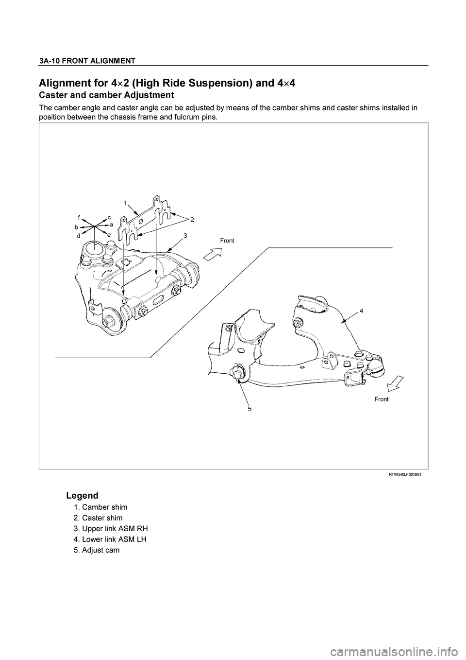
Caster and camber Adjustment
The camber angle and caster angle can be adjusted by means of the camber shims and caster shims installed in
position between the chassis frame and fulcrum pins.
RTW340LF001901
Legend
1. Camber shim
2. Caster shim
3. Upper link ASM RH
4. Lower link ASM LH
5. Adjust cam
Page 3428 of 4264

3A-12 FRONT ALIGNMENT
Toe-in Adjustment
Measurement should be taken with the vehicle on a surface
plate.
If a surface plate is not available, toe-in should be checked
with the vehicle parked on a level floor.
1. Set front wheels to straight ahead position.
2. Align the toe-in gauge with center height of each wheel a
t
front end.
3.
Apply center marks to each wheel, then take measurement
of distance A between the center marks on each wheel.
4. Slowly move the vehicle rearward until the center marks
reach the rear end position.
5. Take measurement of distance B between the cente
r
marks at rear end.
The toe-in can be calculated with next formula.
Toe-in = B - A
Toe-in mm (in)
4�2 (High ride suspension)
4�4 0�2 (0�0.08)
To adjust the toe-in angle, loosen the lock nuts (2) on the tie
rod (1) and turn the tie rod. Turn both rods the same amount,
to keep the steering wheel centered.
Lock Nut Torque N�
m (kgf�
m/lb�
ft)
98�6.0 (10.0�0.6 / 72.3�4.3)
RTW330SH000201
Trim Height
Trim Height : at Curb Weight
Trim height (Z) = A - B
mm (in)
Z
140�
5 (5.51)
Page 3429 of 4264
FRONT ALIGNMENT 3A-13
450R100002-X
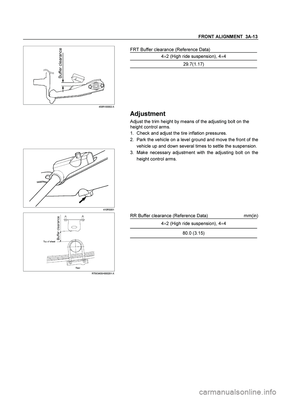
FRT Buffer clearance (Reference Data)
4�2 (High ride suspension), 4�4
29.7(1.17)
Adjustment
Adjust the trim height by means of the adjusting bolt on the
height control arms.
1. Check and adjust the tire inflation pressures.
2. Park the vehicle on a level ground and move the front of the
vehicle up and down several times to settle the suspension.
410RS001
3. Make necessary adjustment with the adjusting bolt on the
height control arms.
RTW340SH000201-X
RR Buffer clearance (Reference Data) mm(in)
4�
2 (High ride suspension), 4�
4
80.0 (3.15)
Page 3438 of 4264
, the pump is")
3B-8 POWER-ASSISTED STEERING SYSTEM
6. Fully close the shutoff valve. Record the highest
pressures.
��
If the pressure recorded is within 9300-9800 kPa
(95-100 kg/cm
2/1350-1420 psi), the pump is
functioning within its specifications.
��
If the pressure recorded is higher than 9800 kPa
(100 kg/cm
2/1420 psi), the valve in the pump is
defective.
��
If the pressure recorded is lower than 9300 kPa (95
kg/cm
2/1350 psi), the valve or the rotating group in
the pump is defective.
7. If the pump pressures are within specifications,
leave the valve open and turn (or have someone
else turn) the steering wheel fully in both directions.
Record the highest pressures and compare with the
maximum pump pressure recorded in step 6. If this
pressure cannot be built in either side of the powe
r
steering unit, the power steering unit is leaking
internally and must be replaced.
8. Shut the engine off, remove the testing gauge.
9. Reconnect the pressure hose, check the fluid level
and make the needed repairs.
10. If the problem still exists, the steering and fron
t
suspension must be thoroughly examined.
Maintenance
The hydraulic system should be kept clean and fluid
level in the reservoir should be checked at regula
r
intervals and fluid added when required. Refer to
Recommended Fluids and Lubricants in General
Information section for the type of fluid to be used and
the intervals for filling.
If the system contains some dirt, flush it as described in
this section. If it is exceptionally dirty, the pump must be
completely disassembled before further usage. (The
steering unit cannot be disassembled.)
All tubes, hoses, and fittings should be inspected for
leakage at regular intervals. Fittings must be tight. Make
sure the clips, clamps and supporting tubes and hoses
are in place and properly secured.
Power steering hoses and lines must not be twisted,
kinked or tightly bent. Air in the system will cause
spongy action and noisy operation. When a hose is
disconnected or when fluid is lost, for any reason, the
system must be bled after refilling. Refer to Bleeding the
Power Steering System in this section.
��
Inspect belt for tightness.
��
Inspect pulley for looseness or damage. The pulle
y
should not wobble with the engine running.
��
Inspect hoses so they are not touching any othe
r
parts of the vehicle.
��
Inspect fluid level and fill to the proper level.
Fluid Level
1. Run the engine until the power steering fluid
reaches normal operating temperature, about 55�
C (130�
F), then shut the engine off.
2. Check the level of fluid in the reservoir.
3. If the fluid level is low, add power steering fluid as
specified in General Information to the proper level
and install the receiver cap.
4. When checking the fluid level after the steering
system has been serviced, air must be bled from
the system. Refer to Bleeding the Power Steering
System in this section.
Bleeding The Power Steering System
When a power steering pump or unit has been installed,
or an oil line has been disconnected, the air that has
entered the system must be bled out before the vehicle
is operated. If air is allowed to remain in the powe
r
steering fluid system, noisy and unsatisfactory operation
of the system may result.
Bleeding Procedure
When bleeding the system, and any time fluid is added
to the power steering system, be sure to use only powe
r
steering fluid as specified in General Information.
1. Fill the pump fluid reservoir to the proper level and
let the fluid settle for at least two minutes.
2. Start the engine and let it run for a few seconds. Do
not turn the steering wheel. Then turn the engine
off.
3. Add fluid if necessary.
4. Repeat the above procedure until the fluid level
remains constant after running the engine.
5. Raise and support the front end of the vehicle so
that the wheels are off the ground.
6. Start the engine. Slowly turn the steering wheel right
and left, lightly contacting the wheel stops.
7. Add power steering fluid if necessary.
8. Lower the vehicle, set the steering wheel at the
straight forward position after turning it to its full
steer positions 2 or 3 times, and stop the engine.
9. Check the fluid level and refill as required.
10. If the fluid is extremely foamy, allow the vehicle to
set a few minutes, then repeat the above procedure.
Flushing The Power Steering System
1. Raise and support the front end of the vehicle off
the ground until the wheels are free to turn.
2. Remove the fluid return line at the pump inlet
connector and plug the connector port on the pump.
Position the line toward a large container to catch
the draining fluid.
3. While running the engine at idle, fill the reservoi
r
with new power steering fluid. Turn the steering
wheel in both directions. Do not contact or hold the
steering wheel to the wheel stops. This will cause
the pump to go to pressure relief mode, which ma
y
cause a sudden fluid overflow at the reservoir.
Page 3493 of 4264

FRONT SUSPENSION 3C-1
SECTION 3C
FRONT SUSPENSION
TABLE OF CONTENTS
PAGE
Main Data and Specifications ........................................................................................... 3C- 2
Torque Specifications ....................................................................................................... 3C- 3
Special Parts Fixing Nuts and Bolts ............................................................................ 3C- 3
Front Suspension .............................................................................................................. 3C- 6
General Description ...................................................................................................... 3C- 6
Front Suspension (4�
�� �2 Except High Ride Suspension)............................................. 3C- 8
Front Suspension (4
�
�� �2 High Ride Suspension, 4
�
�� �4) ................................................. 3C- 30
Troubleshooting ............................................................................................................ 3C- 54