Page 235 of 4264

FRONT WHEEL DRIVE 4C1-15
Removal
1. Jack up the vehicle and support it using jack stand.
2. Remove the tire and wheel.
3. Remove the stone guard.
4. Remove the brake caliper fixing bolt and hang the caliper.
Refer to Disc Brakes in Brake section.
5. Remove the antilock brake system speed sensor.
Refer to Front Wheel Speed Sensor in Brake section.
6. Remove the hub and disc assembly.
Refer to Front Hub and Disc in this section.
7. Remove the propeller shaft, refer to Front Propeller Shaft in
this section.
8. Loosen the height control arm of the torsion bar, then
remove the torsion bar from lower control arm.
Refer to Torsion Bar in Suspension section.
9. Remove the suspension crossmember.
10. Remove the lower nut (1) of the stabilizer link.
11. Remove the lower bolt and nut (2) of the shock absorber.
12. Remove the tie-rod end from the knuckle.
Refer to Power Steering Unit in Steering Section.
13. Disconnect the breather hose of the front axle.
14. Disconnect the actuator connector. (With shift on the fly)
15. Remove the bolts and nuts of the lower control arm (Frame
side), then disconnect the lower control arm from frame.
16. Disconnect between the right side upper control arm and
the knuckle, then remove the knuckle with lower control
arm.
CAUTION :
When removing the knuckle, be careful not to damage the
oil seal inside of the knuckle.
Page 236 of 4264

4C1-16 FRONT WHEEL DRIVE
17. Support the differential case by the jack.
18. Remove the front axle mounting bolts and nuts, lower the
jack slowly. Remove the left side drive shaft end from the
knuckle, then lower the axle assembly from the vehicle.
CAUTION :
1. During the work, be sure that the axle assembly is
supported securly.
2. Be careful not to damage the bellows of the power
steering unit by interference.
3. Be careful not to damage the breater pipe and breater
pip bracket of the shift on the fly by interference.
Installation
1. Support the differential case by the jack.
2. Jack up the front drive axle assembly, install the left side
drive shaft to the knuckle, then install the mount bolts and
nuts.
CAUTION :
1. Be careful not to damage the bellows of the power
steering unit by interference.
2. Be careful not to damage the breater pipe and breater
pip bracket of the shift on the fly by interference.
3. When installing the drive shaft to the knuckle, be
careful not to damage the oil seal inside of the knuckle.
RTW34CSH000101
3. Tighten the mounting bolts and nuts to the specified torque.
Torque : 169 N·m (17.2kg·m/124 lb ft)
4. Install the right side knuckle with lower control arm to the
upper control arm.
Refer to Knuckle in Suspension section.
CAUTION :
When insert the drive shaft to the knuckle, be careful not
to damage the oil seal inside of the knuckle.
5. Align the bolt hole of the lower control arm, install the bolts
and nuts.
Page 237 of 4264

FRONT WHEEL DRIVE 4C1-17
NOTE :
Adjust the buffer clearance before tighten the bolts and nuts of
the lower control arm.
6. Install the breather hose of the front axle.
7. Install the actuator connector of the shift on the fly. (With
shift on the fly)
8. Install the tie-rod end of the power steering unit to the
knuckle, tighten the nut to the specified torque.
Torque : 98 N·m (10.0kg·m/73 lb ft)
9. Install lower bolts and nuts of the shock absorber, tighten it
to the specified torque.
Torque : 93 N·m (9.5kg·m/69 lb ft)
10. Install lower nuts of the stabilizer link, tighten it to the
specified torque.
Torque : 50 N·m (5.1kg·m/37 lb ft)
11. Install the suspension crossmember.
12. Install the torsion bar.
Refer to Torsion Bar in Suspension section.
13. Install the front propeller shaft.
Refer to Front Propeller Shaft in this section.
14. Install the hub and disc assembly and adjust the bearing
preload.
Refer to Front Hub and Disc in this section.
15. Install the wheel speed sensor of the antilock brake
system.
16. Install the brake caliper. Tighten the bolt of the caliper
bracket to the specified torque.
Torque : 155 N·m (15.8kg·m/115 lb ft)
17. Install the stone guard.
18. Install the tire and wheel.
19. Lower the vehicle, adjust the trim height.
Refer to Trim Height Adjustment in Steering section.
20. Tighten the bolts and nuts of the lower control arm to the
specified torque.
Refer to Lower Control Arm in Suspension section.
Page 262 of 4264
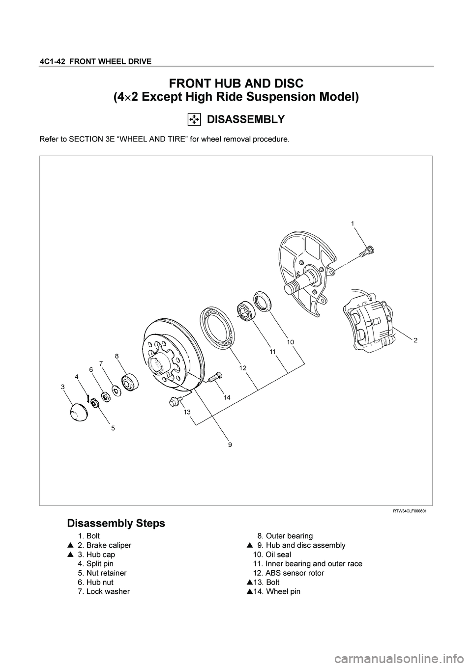
4C1-42 FRONT WHEEL DRIVE
FRONT HUB AND DISC
(4�
�� �2 Except High Ride Suspension Model)
DISASSEMBLY
Refer to SECTION 3E “WHEEL AND TIRE” for wheel removal procedure.
RTW34CLF000801
Disassembly Steps
1. Bolt
�
2. Brake caliper
�
3. Hub cap
4. Split pin
5. Nut retainer
6. Hub nut
7. Lock washer
8. Outer bearing
�
9. Hub and disc assembly
10. Oil seal
11. Inner bearing and outer race
12. ABS sensor rotor
�
13. Bolt
�
14. Wheel pin
Page 270 of 4264
4C1-50 FRONT WHEEL DRIVE
FRONT HUB AND DISC
(4�
�� �4, 4�
�� �2 High Ride Suspension,
4�
�� �
4 Rigid Hub, 4�
�� �
4 Shift On the Fly Model)
DISASSEMBLY
Refer to SECTION 3E “WHEEL AND TIRE” for wheel removal procedure
411R300011
Disassembly Steps
1. Bolt
2. Hub cap
3. Snap ring and shim (4�
4 model only)
4. Flange (4�
4 model only)
5. Lock washer
�
6. Hub nut
�
7. Hub and disc assembly
8. Outer bearing
9. Oil seal
10. Inner bearing
11. ABS sensor rotor
�
12. Bolt
�
13. Wheel pin
Page 288 of 4264
4C1-68 FRONT WHEEL DRIVE
4�
�� �
2 Model
1. WANDERS AND PULLS
Checkpoint Trouble Cause Countermeasure
Adjust the wheel bearing
preload
Too tight
NG
Adjust the front alignment
Front alignment
Incorrect
Steering unit
Tighten or replace
Loose or worn
NG NG
Suspension
Tighten or replace
Replace or adjust the inflation
Front or rear suspension parts
loose or broken
Tire
Worn or improperly inflated
OK
NG NG OK OK
OK
Wheel bearing preload
Page 292 of 4264
4C1-72 FRONT WHEEL DRIVE
5. WANDERS AND PULLS
Checkpoint Trouble Cause Countermeasure
Adjust the wheel bearing
preload
Too tight
NG
Adjust the front alignment
Front alignment
Incorrect
Tighten or replace
Steering unit
Loose or worn
NG NG
OK OK
Tighten or replace
Replace or adjust the inflation
Suspension
Front or rear suspension parts
loose or broken
Tab
Worn or improperly inflated
NG NG
OK OK
Wheel bearing preload
Page 448 of 4264
 Outline
When the LSPV (Load Sensing Proportioning Valve)
detects a change in load weight, the load sensing spring
stretches.
Its reactio")
5C-22 BRAKES
RTW35CSH001001
�
�� � Operation
1) Outline
When the LSPV (Load Sensing Proportioning Valve)
detects a change in load weight, the load sensing spring
stretches.
Its reaction force is transmitted to the bottom of the load
sensing valve to secure an optimum rear wheel cylinde
r
fluid pressure break point in proportion to the actual load
weight.
Besides, if the front brake system should fail, the device is
designed to prevent the master cylinder fluid pressure from
decreasing and to apply it directly to the rear wheel cylinde
r
to obtain a sufficient braking performance.
RTW35CSH001101
2) Bellow cutting point.
The Force (F) keeps the main piston (1) the rest position.
The inlet pressure (A) and outlet pressure (B) are the same
as well as the inlet pressure (C) from front master cylinder.
The bypass piston (2) is kept on rest position by equilibrium
of the pressures (A) and (C) and the bypass spring load (3).
RTW35CSH001201
3) Cutting point.
The cutting point is given by relation between force (F), tha
t
is the load applied by suspension of the vehicle and the
main piston area (1). The cutting point is achieved when the
force generated by hydraulic pressure is upper than the
force (F) given by the load suspension. The main piston (1)
moves from the rest position closing the valve. In this
moment the inlet pressure (A) is upper than the outle
t
pressure (B). The bypass piston (2) continues on the res
t
position by equilibrium of (A) and (C) pressure.