Page 3798 of 4264
7A3-42 ON-VEHICLE SERVICE (AW30 –40LE)
Transmission Assembly
Transmission and Associated Parts
Legend
(9) Under Cover
(1) Rear Propeller Shaft (10) Flex Plate Torque Converter bolt
(2) Front Propeller Shaft (4WD only) (11) Shift Cable
(3) Middle Exhaust Pipe (12) Rear Mount Rubber
(4) Transfer Case Assembly (4WD only) (13) Heat Protector
(5) Fuel Pipe Clip and Bracket (14) Transmission Crossmember
(6) ATF Pipe and Clip (15) Transmission Assembly (2WD)
(7) Oil Level Gauge and Guide Tube (16) Transmission Assembly (4WD)
(8) Suspension Crossmember
Page 3799 of 4264
 7A3-43
Removal
NOTE: Before removing transmission and transfer
assembly from vehicle, change the transfer mode to
2WD using the 4WD push button switch on dash")
ON-VEHICLE SERVICE (AW30 –40LE) 7A3-43
Removal
NOTE: Before removing transmission and transfer
assembly from vehicle, change the transfer mode to
2WD using the 4WD push button switch on dash panel.
1. Disconnect battery ground cable.
2. Raise and support vehicle with suitable stands.
3. Remove front propeller shaft.(4WD only)
NOTE: Apply alignment marks on the flange at both
front and rear sides.
4. Remove rear propeller shaft.
NOTE: Apply alignment marks on the flange at the
differential side.
401RS023
5. Remove the middle exhaust pipe.
RTW37ASH0001
6. Disconnect the transfer harness connectors and the
clips.(4WD only)
Speed sensor
2W-4W shift actuator
NOTE: Avoid turning the vehicle ignition switch to the
ON position when the 2WD-4WD connector is removed
(battery connected).
If the ignition switch must be turned to the ON position,
the controller must first be removed (memory must be
cleared because the CHECK 4WD INDICATOR will
light).
7. Support transfer case with a transmission jack.(4WD only)
8. Remove the transfer case assembly from the
transmission.(4WD only)
9. Disconnect the shift cable.
10. Remove the fuel pipe clips with the fuel pipes from the brackets and put aside it. Remove the fuel pipe
brakets from the transmission.
P1010010
11. Discinnect the transmission harness connectors
and clips.
12. Remove the oil level gauge and the guide tube.
13. Remove the suspension crossmember.
Page 3804 of 4264
7A3-48 ON-VEHICLE SERVICE (AW30 –40LE)
11. Install the suspension crossmember.
Torque: 65 N �
��
�
m (6.6 kg �
��
�
m/48 lb ft)
12. Install filler tube and insert oil level gage.
Torque: 22 N �
��
�
m (2.2 kg �
��
�
m/16 lb ft)
13. Install select cable by connecting inner cable to
select lever and installing outer cable with bracket.
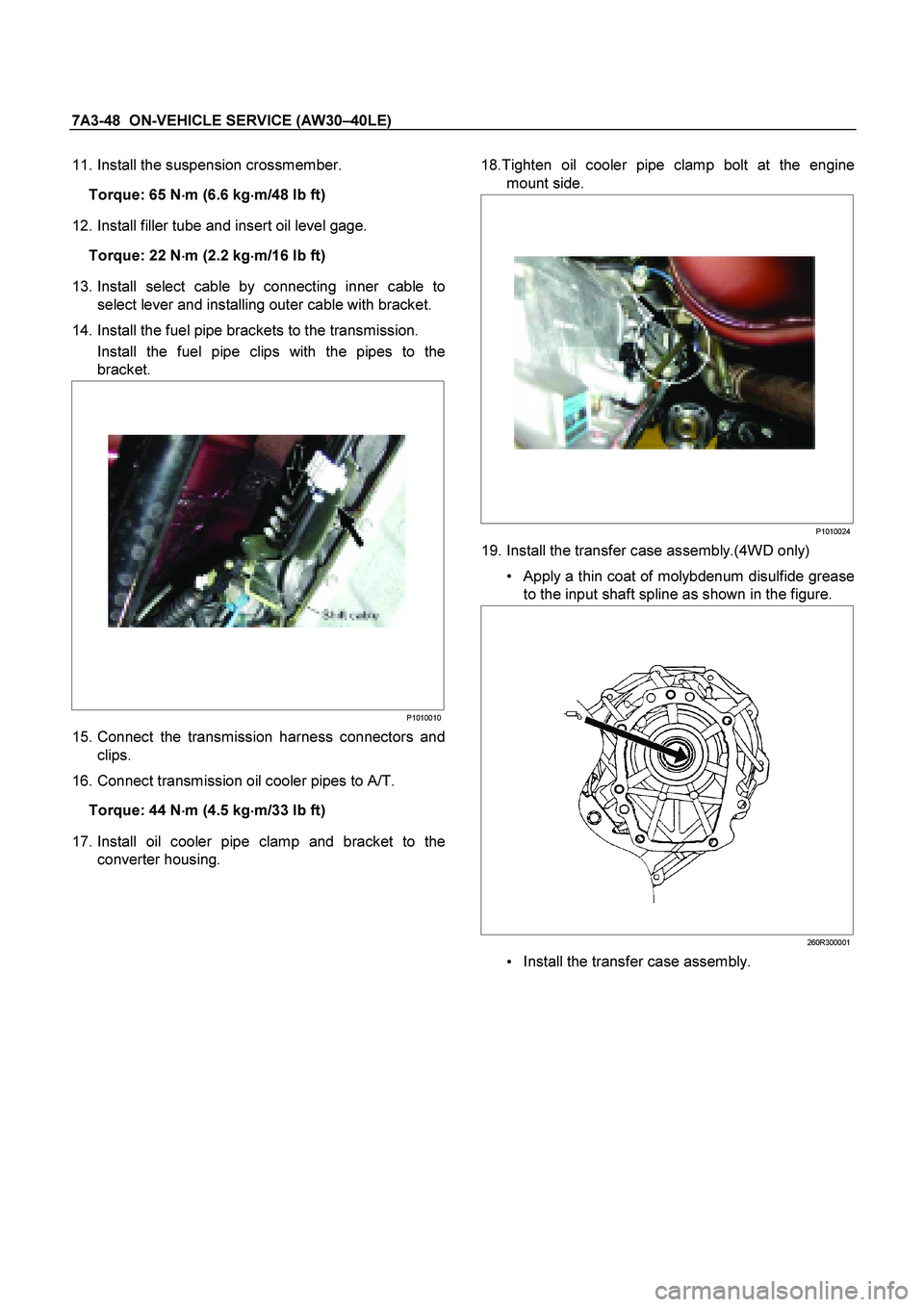
14. Install the fuel pipe brackets to the transmission. Install the fuel pipe clips with the pipes to the
bracket.
P1010010
15. Connect the transmission harness connectors and
clips.
16. Connect transmission oil cooler pipes to A/T.
Torque: 44 N �
��
�
m (4.5 kg
�
��
�
m/33 lb ft)
17. Install oil cooler pipe clamp and bracket to the
converter housing.
18.Tighten oil cooler pipe clamp bolt at the engine
mount side.
P1010024
19. Install the transfer case assembly.(4WD only)
Apply a thin coat of molybdenum disulfide grease
to the input shaft spline as shown in the figure.
260R300001
Install the transfer case assembly.
Page 4095 of 4264
DIAGNOSIS (JR405E) 7A2-103
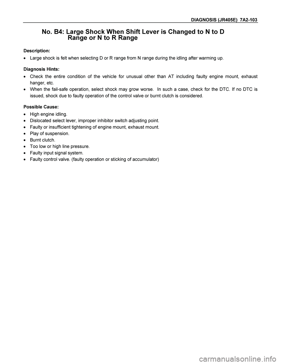
No. B4: Large Shock When Shift Lever is Changed to N to D
Range or N to R Range
Description:
� Large shock is felt when selecting D or R range from N range during the idling after warming up.
Diagnosis Hints:
� Check the entire condition of the vehicle for unusual other than AT including faulty engine mount, exhaust
hanger, etc.
� When the fail-safe operation, select shock may grow worse. In such a case, check for the DTC. If no DTC is
issued, shock due to faulty operation of the control valve or burnt clutch is considered.
Possible Cause:
� High engine idling.
� Dislocated select lever, improper inhibitor switch adjusting point.
� Faulty or insufficient tightening of engine mount, exhaust mount.
� Play of suspension.
� Burnt clutch.
� Too low or high line pressure.
� Faulty input signal system.
� Faulty control valve. (faulty operation or sticking of accumulator)

Transmission Assembly
Transmission and Associated Parts
Legend
(9) Under Cover
(1) Rear Propeller Shaft (10) Flex Plate Torque Co")