Page 3558 of 4264
3D-2 REAR SUSPENSION
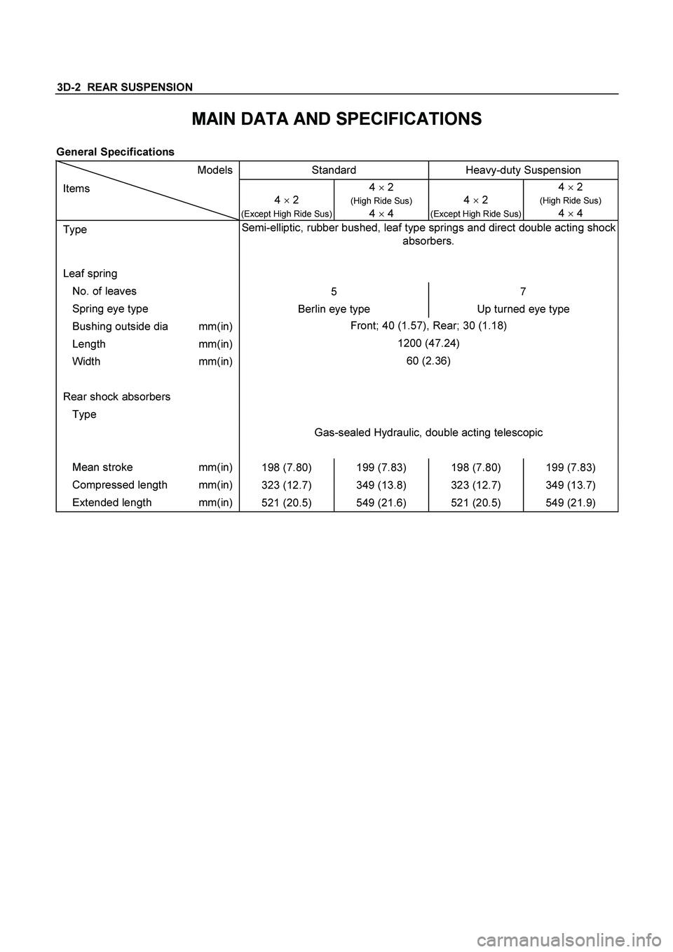
MAIN DATA AND SPECIFICATIONS
General Specifications
Models Standard Heavy-duty Suspension
Items
4 � 2
(Except High Ride Sus)
4 � 2
(High Ride Sus)
4
� 4
4 � 2 (Except High Ride Sus) 4 � 2
(High Ride Sus)
4
� 4
Type Semi-elliptic, rubber bushed, leaf type springs and direct double acting shock
absorbers.
Leaf spring
No. of leaves
5 7
Spring eye type
Berlin eye type Up turned eye type
Bushing outside dia mm(in) Front; 40 (1.57), Rear; 30 (1.18)
Length mm(in) 1200 (47.24)
Width mm(in) 60 (2.36)
Rear shock absorbers
Type
Gas-sealed Hydraulic, double acting telescopic
Mean stroke mm(in)
198 (7.80) 199 (7.83) 198 (7.80) 199 (7.83)
Compressed length mm(in)
323 (12.7) 349 (13.8) 323 (12.7) 349 (13.7)
Extended length mm(in)
521 (20.5) 549 (21.6) 521 (20.5) 549 (21.9)
Page 3559 of 4264
REAR SUSPENSION 3D-3
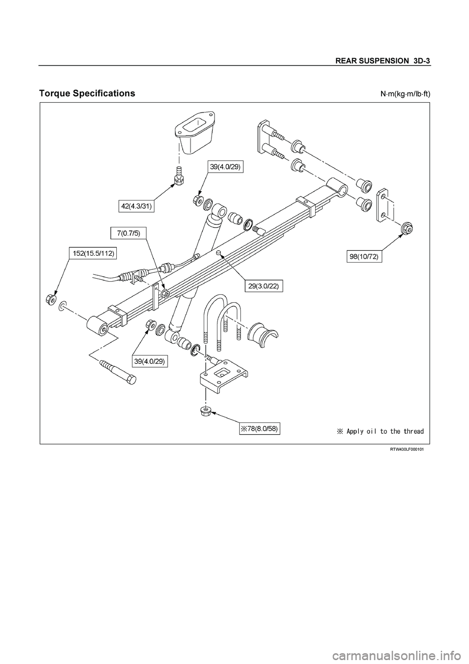
Torque Specifications
N
�m(kg
�m/lb
�ft)
RTW430LF000101
Page 3560 of 4264
3D-4 REAR SUSPENSION
REAR SUSPENSION
GENERAL DESCRIPTION
Rear suspension absorbs vibration from the road surface thus preventing vehicle damage, as well as providing a
good ride.
Components parts
� Spring between the body and the axle case
� Spring shackle connecting the spring to the body
� Clamp and U-bolt fixing the axle case to the spring
� Shock absorber as a countermeasure for vibration
Page 3561 of 4264
REAR SUSPENSION 3D-5
LEAF SPRING AND SHOCK ABSORBER
LEAF SPRING AND ASSOCIATED PARTS
460R300001
Legend
1. Parking Brake Cable Bracket
2. Nut and Washer
3. Nut and Washer
4. Shock Absorber
5. Nut
6. U Bolt and Seat
7. Lower Clamp
8. Nut
9. Shackle Plate
10. Shackle Pin
11. Rubber Bushing
12. Nut and Plain Washer
13. Spring Pin
14. Leaf Spring
15. Bump Rubber
Page 3562 of 4264

3D-6 REAR SUSPENSION
F03L100003
Removal
� Jack up the rear axle and place chassis stands under the
frame near the front end of the rear spring brackets.
Note:
� Be careful not to stretch the flexible brake hose o
r
parking brake cable.
� Support the vehicle on the specified jack point.
1. Remove the parking brake cable (1) from the leaf spring.
2. Loosen the shock absorber fixing nut and remove the nu
t
and special washer (2) from the lower clamp.
3. Remove the shock absorber fixing nut and washer (3) at
frame side.
4. Lifting the rear axle by a jack, remove the shock absorbe
r
(4) and lower the jack.
5. Remove the U bolt fixing nut (5).
6. Take out the U bolt (6), seat and lower clamp (7).
7. Support the leaf spring by a jack and remove the shackle
pin fixing nuts (8).
8. Drive out the shackle pin (10), using a brass bar and
hammer.
9. Remove the shackle plate (9) and rubber bushings (11).
10. Remove the nut (12) and drive out the shackle with a
hammer using a brass bar.
11. Remove the leaf spring (14).
12. Remove the bump rubber (15).
Page 3563 of 4264
REAR SUSPENSION 3D-7
INSPECTION AND REPAIR
Make correction or parts replacement if wear, damage or their abnormal conditions are found through inspection.
Visual Check
Inspect the following parts for wear, damage, nuts or other
abnormal conditions.
� Leaf spring assembly
� Clip
� Center bolt
� U-bolt
� Spring pin
� Shackle pin
� Shock absorber
� Rubber bumper
� Rubber bushing
� Bump rubber seat
Shackle Pin
Shackle Pin diameter mm (in)
17.93 - 18.00 (0.706 - 0.709)
Spring Pin
Spring Pin Diameter mm (in)
13.8 - 14.0 (0.543 - 0.551)
Shock Absorber
Inspection operation of shock absorber
If no resistance is felt while expanding the shock absorber, that
indicates the absorber is faulty.
Page 3564 of 4264
 and bolt and tighten it to the
specified torque.
Torque N�m (kg�m/lb�ft)
42 (4.3/31)
2. Install the leaf spring (14).
�")
3D-8 REAR SUSPENSION
Installation
1. Install the bump rubber (15) and bolt and tighten it to the
specified torque.
Torque N�m (kg�m/lb�ft)
42 (4.3/31)
2. Install the leaf spring (14).
� The leaf spring assembly should be installed so that the
built-in rubber bush is toward the front.
� Align the holes of the spring eye and frame bracket.
� Insert the spring pin (13) toward vehicle inner side
through the frame bracket holes and the spring bush
hole.
� Tighten the nut (12) a little and after the vehicle is
lowered, tighten it to the specified torque.
Torque N
�m (kg
�m/lb
�ft)
152 (15.5/112)
RTW340LF000101
� Apply rubber grease to inside and outside of the rubber
bushing.
� Install the rubber bushings (11) into the hole of the
frame side bracket and the spring rear eye.
� Install the shackle pin (10) and shackle plate (9).
� Tighten the nuts (8) a little and after vehicle is lowered,
tighten it to the specified torque.
Torque N�m (kg�m/lb�ft)
98 (10/72)
3. Support the lower clamp (7) under the leaf spring.
4. Apply oil to the thread portion of U bolt (6).
Install the U bolt and seat on the rear axle and insert the U
bolt in the lower clamp holes.
5. Tighten the nut (5) to the specified torque.
Torque N�m (kg�m/lb�ft)
78 (8.0/58)
6. Install the shock absorber (4) and inner washer on the
lower clamp pin and frame side pin.
7. Install the washer and nut (3) on the frame side pin and
tighten the nut to the specified torque.
Torque N�m (kg�m/lb�ft)
39 (4.0/29)
8. Install the washer and nut (2) on the lower clamp pin and
tighten the nut to the specified torque.
Torque N�m (kg�m/lb�ft)
39 (4.0/29)
9. Install the parking brake cable (1) on the leaf spring and
tighten the nut at its bracket.
Torque N
�m (kg
�m/lb
�ft)
7 (0.7/5)
Page 3565 of 4264
REAR SUSPENSION 3D-9
LEAF SPRING ASSEMBLY
F03L100004
Disassembly
1. Remove the bushing using a bench press and a suitable
metal fitting.
RTW430SH000101
2. Apply a setting mark across the springs before
disassembling the leaf spring assembly.
F03L100006
3. Use a bench press and remove the center bolt.
� Discard center bolt and install a new one.
465R300001
4. Disassemble the leaf spring assembly.
Inspection and Repair
Inspect leaf spring, bush, clips, liners and center spacer for
wear, damage, rust or other abnormal conditions and if
necessary, repair or replace it.