Page 669 of 4264
ELECTRICAL-BODY AND CHASSIS 8A-11
SYMBOLS AND ABBREVIATIONS
SYMBOLS
Symbol Meaning of Symbol Symbol Meaning of Symbol
Fuse
Bulb
Fusible link
Double filament bulb
Fusible link wire
Motor
Switch
Variable resistor Rheostat
Switch
Coil (inductor), solenoid,
magnetic valve
Switch (Normal close type)
Contact wiring
Relay
Battery
Diode
Connector
Electronic Parts
Light emitting diode
Resistor
Reed switch
Speaker
Condenser
Buzzer
Horn
Circuit breaker
Vacuum switching valve
Page 674 of 4264
8A-16 ELECTRICAL-BODY AND CHASSIS
RELAY
Battery and load location may require that a switch be placed
some distance from either component.
This means a longer wire and a higher voltage drop
1. The
installation of a relay between the battery and the load reduces
the voltage drop
2.
Because the switch controls the relay, amperage through the
switch can be reduced.
Relay Specifications and Configurations
Name/
Color Rated
voltage/ Coil
resistance Internal circuit Name/
color Rated
Voltage/Coil
resistance Internal circuit
1T
(MICRO
ISO)
/Black 12V
Approx. 92�
Minimum
operating
voltage: 7V at
20�C (77�F)
1M (MINI
ISO)
/Black 12V Approx.
94� Minimum
operating
voltage: 7V at
20�C (77�F)
1M
(MICRO
ISO)
/Black 12V
Approx. 132-3
� Minimum
operating
voltage: 7V at
20�C (77�F)
1M
(power)/
Black 12V Approx.
94� Minimum
operating
voltage: 7V at
20�C (77�F)
* Relay contact shown in the wiring diagram indicates condition before actuation.
Page 677 of 4264
ELECTRICAL-BODY AND CHASSIS 8A-19
Battery-1
BATTERY
Inspection
1. Check the battery terminals 1 for corrosion.
2. Check the battery cables
2 for looseness.
3. Check the battery case
3 for cracks and other damage.
4. Check the battery electrolyte level.
Battery-2
Battery Replacement
1. Disconnect the battery ground cable 1.
2. Disconnect the battery positive cable
2.
3. Remove the battery clamp
3.
4. Remove the battery
Caution:
It is important that the battery ground cable be removed
first.
Removing the battery positive cable first can result in a
short circuit.
Jump Starting the Engine with a Booster Battery
The following description assumes that you are using a booster
battery mounted on a second vehicle.
The listed steps (with some minor modifications) are also
applicable if you are using a naked booster battery or special
battery charging equipment.
Page 678 of 4264

8A-20 ELECTRICAL-BODY AND CHASSIS
Caution:
Never push or tow the vehicle in an attempt to start it.
Extensive damage to the emission system and other
vehicle parts will result.
(Only catalytic converter vehicle)
Treat both the discharged battery and the booster battery
with great care when using jumper cables.
Carefully follow the procedure outlined below.
Always be aware of the dangers of sparking.
Failure to follow the following procedure can result in:
a. Serious personal injury, specially to your eyes.
b. Extensive property damage from a battery explosion,
battery acid discharge, or electrical file.
c. Extensive damage to the electronic components o
f
both vehicles.
Do not use a 24 volt booster battery.
Serious damage to the vehicle's electrical system and
electronic components will result.
Jump Starting Procedure
1. Set the parking brake on both vehicles.
2. If one or both vehicles is equipped with a manual
transmission, place the gear shift in the "NEUTRAL"
position.
3. Turn off the ignition on both vehicles.
4. Turn off all vehicle lights and accessories.
5 Be sure that the two vehicles are not touching.
Attach the end of one jumper cable to the booster battery
positive terminal.
6
Attach the other end of the same cable to the discharged
battery positive terminal.
7. Once again, check that the booster battery has a 12 vol
t
rating.
8.
Attach one end of the remaining booster cable to the
booster battery negative terminal.
9.
Attach the other end of the booster cable to a solid ground
(such as the air conditioner compressor mounting bracke
t
or the alternator mounting bracket) in the engine room o
f
the vehicle with the discharged battery.
Be sure that the ground connection is at least 500 mm (20
in) from the discharged battery.
Page 679 of 4264
ELECTRICAL-BODY AND CHASSIS 8A-21
Caution:
Do not attach the booster cable to the discharged battery
negative terminal.
11. Start the engine of the vehicle with the booster battery.
Check that all unnecessary electrical accessories are off.
12. Start the engine of the vehicle with the discharged battery.
13. Remove the jumper cables in the reverse order to which
they were attached.
Caution:
Be absolutely sure to remove the negative jumper cable
from the vehicle with the discharged battery first.
Page 746 of 4264
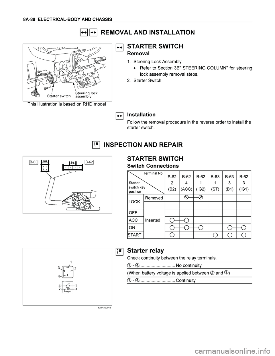
8A-88 ELECTRICAL-BODY AND CHASSIS
REMOVAL AND INSTALLATION
This illustration is based on RHD model
STARTER SWITCH
Removal
1. Steering Lock Assembly
� Refer to Section 3B" STEERING COLUMN" for steering
lock assembly removal steps.
2. Starter Switch
Installation
Follow the removal procedure in the reverse order to install the
starter switch.
INSPECTION AND REPAIR
STARTER SWITCH
Switch Connections
Terminal No.
Starter
switch key
position B-62
2
(B2)B-62
4
(ACC)B-62
1
(IG2) B-63
1
(ST) B-63
3
(B1)B-62
3
(IG1)
Removed
OFF
ACC Inserted
ON
START
LOCK
825R300046
Starter relay
Check continuity between the relay terminals.
1 - 4............................. No continuity
(When battery voltage is applied between 2 and 3)
1 - 4............................. Continuity
Page 778 of 4264
8A-120 ELECTRICAL-BODY AND CHASSIS
TROUBLE SHOOTING
HEADLIGHT
1. Both the headlights (high and low beam) do not light
Checkpoint Trouble Cause Countermeasure
Repair the wiring
Poor ground point contact
NG
Repair open circuit or
connector contact
Repair open circuit
Repair or replace the
combination switch
Voltage between 1
B-60 -
ground
Open circuit between lighting
relay and lighting switch
Open circuit between battery
positive terminal and lighting
relay
Combination switch continuity
Poor switch contact or sw
faulty
Voltage between
5
X-12 - ground and
2
X-12 - ground
Reinstall or replace the
lighting relay
Lighting relay
Poor relay contact or relay
faulty
NG NG NG NG OK
OK
OK OK
Ground point contact (C-36)
Repair open circuit
Wiring continuity between
B-60 - C-36
Open circuit
NG OK
Page 781 of 4264
ELECTRICAL-BODY AND CHASSIS 8A-123
7. Passing light does not function when dimmer switch is operated
Checkpoint Trouble Cause Countermeasure
Repair or replace the dimmer
switch
Dimmer switch
Poor switch point contact
NG
Repair open circuit between
4
X-12 - 3 B-60
Voltage between
3
B-60 - ground (Should
be battery voltage present)
Open circuit
NG OK
8. Headlight beam does not change when dimmer switch is operated
Repair or replace the dimmer
switchDimmer switchLoose beam lever or foreign
material in switch NG


 do not light
Checkpoint Trouble Cause Countermeasure
Repair the wiring
Poor")
