Page 393 of 4264
BRAKE CONTROL SYSTEM 5A-77
DTC C0267 (Flash Code 67) ABS Motor Shorted to Ground
DTC C0268 (Flash Code 68) ABS Motor Shorted to Battery
RTW45AMF000201
Step Action
Value(s) Yes No
1 Was the “Basic Diagnostic Flow Chart” performed?
- Go to Step 2 Go to Basic
Diagnostic
Flow Chart
2 1. Ignition “OFF”.
2. Check the EHCU circuit for an open, short to
ground, or short to voltage. Also, check the EHCU
ignition feed circuit for an open or short to ground
and the EHCU ground circuit for an open or short to
voltage.
3. If a problem is found, repair as necessary.
Was a problem found?
- Verify repair Go to Step 3
3 1. Ignition “ON,” engine “OFF.”
2. Select “Display DTCs” with the Tech 2.
Note: Perform the various tests (actuator test, test
run, brake test, etc.) then observe the DTC with a
Tech2.
Are any DTCs stored? - Go to Step 4 Verify repair
Page 398 of 4264
5A-82 BRAKE CONTROL SYSTEM
DTC C0276 (Flash Code 76) G-Sensor Malfunction
RTW35AMF000301
Step Action
Value(s) Yes No
1 Was the “Basic Diagnostic Flow Chart” performed?
- Go to Step 2 Go to Basic
Diagnostic
Flow Chart
2 1. Check for a poor connection at the G-sensor
harness connector.
2. If a problem is found, repair as necessary.
Was a problem found?
- Verify repair Go to Step 3
3 1. Ignition “OFF”, disconnect the G-sensor and
EHCU.
2. Ignition “ON”, engine “OFF”.
3. Check the supply voltage to G-sensor.
Was the value normal? Battery
Voltage Go to Step 5 Go to Step 4
4 Repair or replace the power supply circuit.
Was the action complete? - Verify repair -
5 1. Check the circuit between EHCU and G-sensor.
(Circuit for an open, short to ground, or short to
voltage.)
2. If a problem is found, repair as necessary.
Was a problem found?
- Verify repair Go to Step 6
Page 400 of 4264
5A-84 BRAKE CONTROL SYSTEM
DTC C0277 (Flash Code 77) Power Supply Low Input
DTC C0278 (Flash Code 78) Power Supply High Input
RTW45AMF000201
Step Action
Value(s) Yes No
1 Was the “Basic Diagnostic Flow Chart” performed?
- Go to Step 2 Go to Basic
Diagnostic
Flow Chart
2 1. Check for a poor connection at EHCU
2. If a problem is found, repair as necessary.
Was a problem found?
- Verify repair Go to Step 3
3 1. Ignition “OFF”, disconnect EHCU.
2. Ignition “ON”, engine “OFF”.
3. Check the supply voltage to EHCU.
Was the value normal? Battery
Voltage Go to Step 5 Go to Step 4
4 Repair or replace the power supply circuit.
Was the action complete? - Verify repair -
5 1. Check the power supply circuit.
(Circuit for an open, short to ground, or short to
voltage.)
2. If a problem is found, repair as necessary.
Was a problem found?
- Verify repair Go to Step 6
Page 488 of 4264
5C-62 BRAKES
360r300003
5. Vacuum Hose
The check valve (2) is built-in to the vacuum hose.
When installing the vacuum hose make sure that the arrow on
the hose is facing the engine (1).
Note :
�
Do not apply oil to the vacuum hose.
�
Installation direction is very important. The booster will no
t
operate if the vacuum hose is installed in the wrong
direction.
4JA1-T/4JA1-TC/4JH1-TC LHD model (with 2nd Battery)
RTW45CLF000101
Page 489 of 4264
BRAKES 5C-63
4JA1-T/4JA1-TC/4JH1-TC LHD Model (without 2nd Battery)
RTW45CMF0002
4JA1-T/4JA1-TC/4JH1-TC RHD Model
331R300008
Page 659 of 4264

ELECTRICAL-BODY AND CHASSIS 8A-1
SECTION 8A
ELECTRICAL-BODY AND CHASSIS
TABLE OF CONTENTS
PAGE
General Information ........................................................................................................ 8A- 4
Notes for Working on Electrical Items .......................................................................... 8A- 5
Symbols and Abbreviations ........................................................................................... 8A- 11
Symbols ...................................................................................................................... 8A- 11
Abbreviations ............................................................................................................. 8A- 12
Parts for Electrical Circuit .............................................................................................. 8A- 13
Wiring .......................................................................................................................... 8A- 13
Fuse ............................................................................................................................. 8A- 15
Fusible Link ................................................................................................................ 8A- 15
Relay ............................................................................................................................ 8A- 16
Diode ........................................................................................................................... 8A- 17
Connector ................................................................................................................... 8A- 18
Battery ......................................................................................................................... 8A- 19
Reading the Circuit Diagram .......................................................................................... 8A- 22
Parts Location ............................................................................................................ 8A- 22
Circuit Diagram ........................................................................................................... 8A- 23
Connector List ............................................................................................................. 8A- 23
Main Data and Specifications ........................................................................................ 8A- 24
Bulb Specifications .................................................................................................... 8A- 24
Relay and Fuse ................................................................................................................ 8A- 26
Relay and Fuse Box Location ................................................................................... 8A- 26
Relay Location ............................................................................................................ 8A- 28
Page 662 of 4264

8A-4 ELECTRICAL-BODY AND CHASSIS
GENERAL INFORMATION
The body and chassis electrical system operates on a twelve volt power supply with negative ground polarity.
The main harness consists of the engine harness, the instrument harness, the body harness, and the chassis
harness.
The harnesses use a split corrugated tube to protect the wires from the elements.
Wire size is determined by current flow, circuit length, and voltage drop.
All wires have color-coded insulation.
Wire color-codes are shown in the circuit diagrams.
This makes it easier to trace circuits and to make the proper connections.
Each circuit consists of the following:
1. Power source - The battery and the alternator
2. Wires - To carry electrical current through the circuit
3. Fuses - To protect the circuit against current overload
4. Relays - To protect voltage drop between the battery and the circuit parts and to protect the switch points against
burning
5. Switches - To open and close the circuit
6. Load - Any device, such as a light or motor, which converts the electrical current into useful work
7. Ground - To allow the current to flow back to the power source
Page 663 of 4264

ELECTRICAL-BODY AND CHASSIS 8A-5
NOTES FOR WORKING ON ELECTRICAL ITEMS
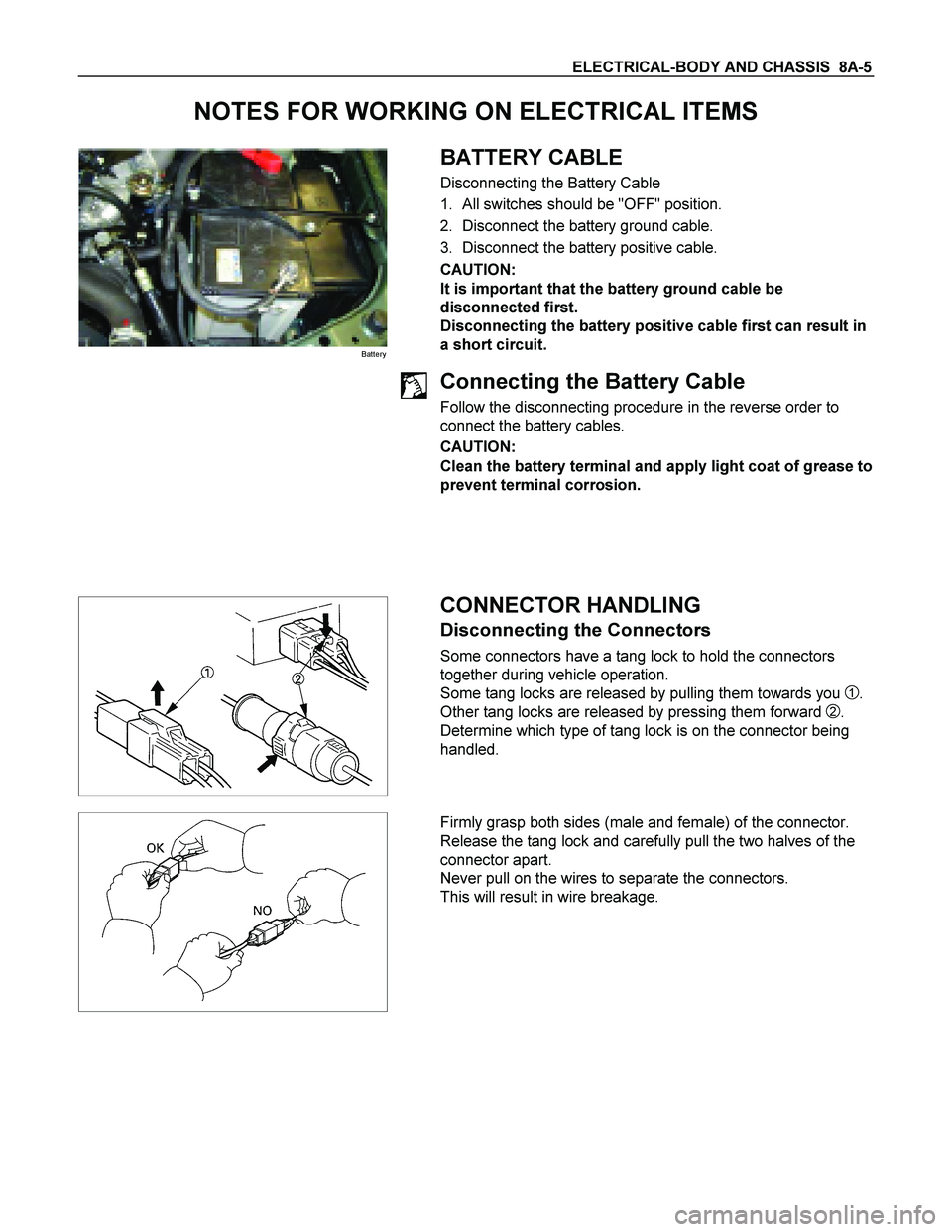
Battery
BATTERY CABLE
Disconnecting the Battery Cable
1. All switches should be "OFF" position.
2. Disconnect the battery ground cable.
3. Disconnect the battery positive cable.
CAUTION:
It is important that the battery ground cable be
disconnected first.
Disconnecting the battery positive cable first can result in
a short circuit.
Connecting the Battery Cable
Follow the disconnecting procedure in the reverse order to
connect the battery cables.
CAUTION:
Clean the battery terminal and apply light coat of grease to
prevent terminal corrosion.
CONNECTOR HANDLING
Disconnecting the Connectors
Some connectors have a tang lock to hold the connectors
together during vehicle operation.
Some tang locks are released by pulling them towards you
1.
Other tang locks are released by pressing them forward
2.
Determine which type of tang lock is on the connector being
handled.
Firmly grasp both sides (male and female) of the connector.
Release the tang lock and carefully pull the two halves of the
connector apart.
Never pull on the wires to separate the connectors.
This will result in wire breakage.