Page 1258 of 4264
6A – 118 ENGINE MECHANICAL
INSTALLATION
EXTERNAL PARTS
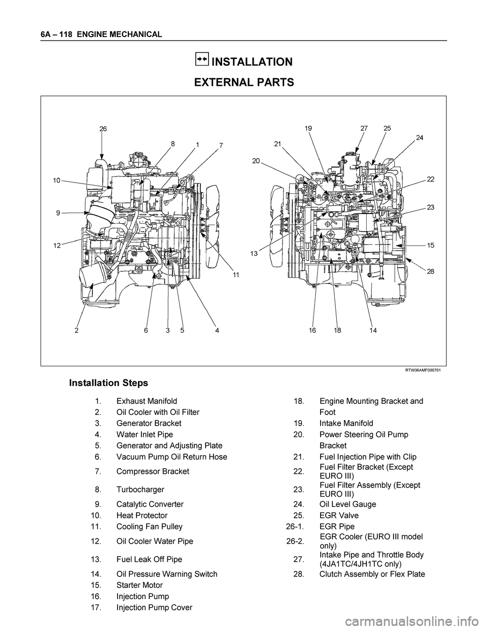
RTW36AMF000701
Installation Steps
1.
Exhaust Manifold 18. Engine Mounting Bracket and
2.
Oil Cooler with Oil Filter Foot
3. Generator Bracket 19. Intake Manifold
4. Water Inlet Pipe 20. Power Steering Oil Pump
5.
Generator and Adjusting Plate Bracket
6.
Vacuum Pump Oil Return Hose 21. Fuel Injection Pipe with Clip
7.
Compressor Bracket 22. Fuel Filter Bracket (Except
EURO III)
8. Turbocharger 23. Fuel Filter Assembly (Except
EURO III)
9. Catalytic Converter 24. Oil Level Gauge
10. Heat Protector 25. EGR Valve
11. Cooling Fan Pulley 26-1. EGR Pipe
12. Oil Cooler Water Pipe 26-2. EGR Cooler (EURO III model
only)
13. Fuel Leak Off Pipe 27. Intake Pipe and Throttle Body
(4JA1TC/4JH1TC only)
14. Oil Pressure Warning Switch 28. Clutch Assembly or Flex Plate
15. Starter Motor
16. Injection Pump
17. Injection Pump Cover
Page 1263 of 4264
ENGINE MECHANICAL 6A – 123
15. Starter Motor
Tighten the starter motor bolts to the specified torque.
Starter Motor Bolt Torque N·m(kg·m/Ib ft)
85 (8.7/63)
16. Injection Pump
17. Injection Pump Cover (4JA1TC/4JH1TC only)
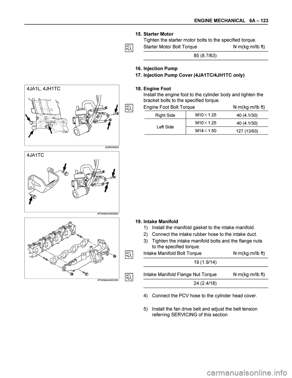
18. Engine Foot
Install the engine foot to the cylinder body and tighten the
bracket bolts to the specified torque.
Engine Foot Bolt Torque N·m(kg·m/Ib ft)
Right Side M10�1.25
40 (4.1/30)
M10�1.25
40 (4.1/30) Left Side
M14�1.50
127 (13/93)
4JA1L, 4JH1TC
022R300003
4JA1TC
RTW46ASH002601
RTW36ASH001001
19. Intake Manifold
1) Install the manifold gasket to the intake manifold.
2) Connect the intake rubber hose to the intake duct.
3) Tighten the intake manifold bolts and the flange nuts
to the specified torque.
Intake Manifold Bolt Torque N·m(kg·m/Ib ft)
19 (1.9/14)
Intake Manifold Flange Nut Torque N·m(kg·m/Ib ft)
24 (2.4/18)
4) Connect the PCV hose to the cylinder head cover.
5) Install the fan drive belt and adjust the belt tension
referring SERVICING of this section
Page 1264 of 4264
6A – 124 ENGINE MECHANICAL
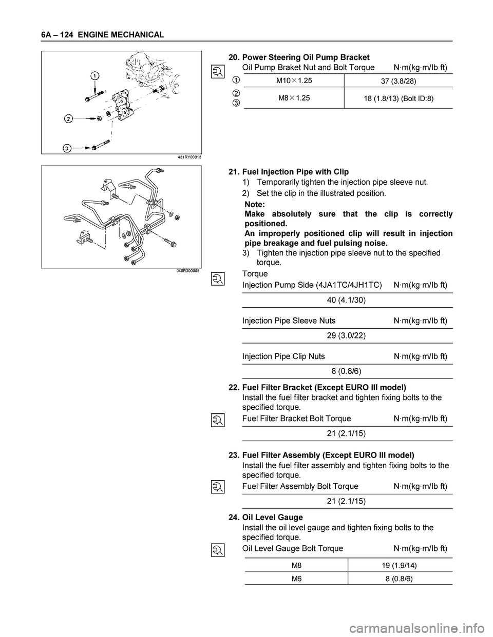
20. Power Steering Oil Pump Bracket
Oil Pump Braket Nut and Bolt Torque N·m(kg·m/Ib ft)
1M10�1.25
37 (3.8/28)
2
3M8�1.25
18 (1.8/13) (Bolt ID:8)
040R300005
21. Fuel Injection Pipe with Clip
1) Temporarily tighten the injection pipe sleeve nut.
2) Set the clip in the illustrated position.
Note:
Make absolutely sure that the clip is correctly
positioned.
An improperly positioned clip will result in injection
pipe breakage and fuel pulsing noise.
3) Tighten the injection pipe sleeve nut to the specified
torque.
Torque
Injection Pump Side (4JA1TC/4JH1TC) N·m(kg·m/Ib ft)
40 (4.1/30)
Injection Pipe Sleeve Nuts N·m(kg·m/Ib ft)
29 (3.0/22)
Injection Pipe Clip Nuts N·m(kg·m/Ib ft)
8 (0.8/6)
22. Fuel Filter Bracket (Except EURO III model)
Install the fuel filter bracket and tighten fixing bolts to the
specified torque.
Fuel Filter Bracket Bolt Torque N·m(kg·m/Ib ft)
21 (2.1/15)
23. Fuel Filter Assembly (Except EURO III model)
Install the fuel filter assembly and tighten fixing bolts to the
specified torque.
Fuel Filter Assembly Bolt Torque N·m(kg·m/Ib ft)
21 (2.1/15)
24. Oil Level Gauge
Install the oil level gauge and tighten fixing bolts to the
specified torque.
Oil Level Gauge Bolt Torque N·m(kg·m/Ib ft)
M8 19 (1.9/14)
M6 8 (0.8/6)
431RY00013
Page 1301 of 4264
FUEL SYSTEM 6C – 1
SECTION 6C
FUEL SYSTEM
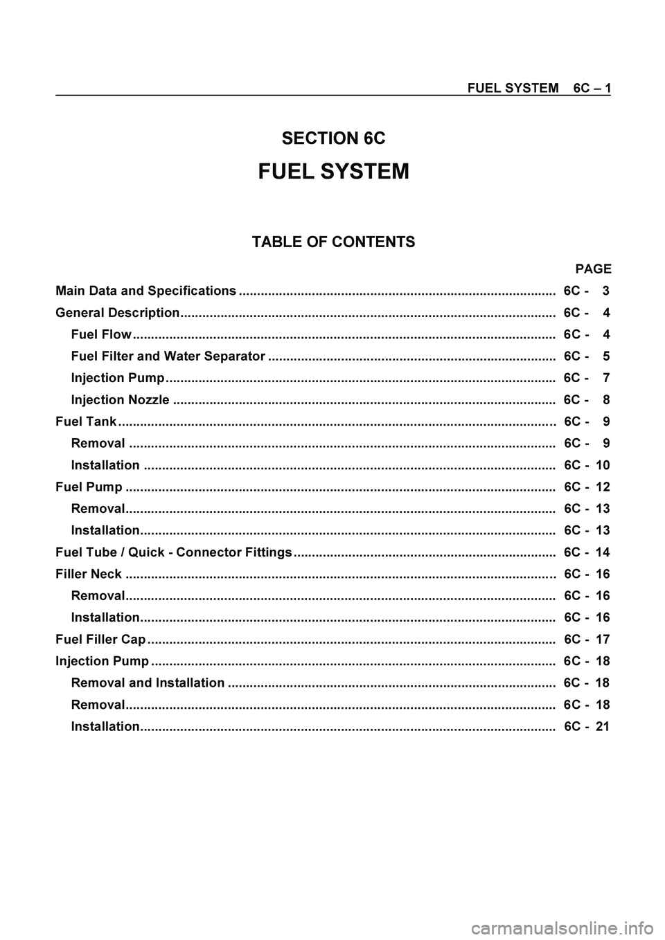
TABLE OF CONTENTS
PAGE
Main Data and Specifications ....................................................................................... 6C - 3
General Description....................................................................................................... 6C - 4
Fuel Flow .................................................................................................................... 6C - 4
Fuel Filter and Water Separator ............................................................................... 6C - 5
Injection Pump ........................................................................................................... 6C - 7
Injection Nozzle ......................................................................................................... 6C - 8
Fuel Tank ........................................................................................................................ 6C - 9
Removal ..................................................................................................................... 6C - 9
Installation ................................................................................................................. 6C - 10
Fuel Pump ...................................................................................................................... 6C - 12
Removal...................................................................................................................... 6C - 13
Installation.................................................................................................................. 6C - 13
Fuel Tube / Quick - Connector Fittings ........................................................................ 6C - 14
Filler Neck ...................................................................................................................... 6C - 16
Removal...................................................................................................................... 6C - 16
Installation.................................................................................................................. 6C - 16
Fuel Filler Cap ................................................................................................................ 6C - 17
Injection Pump ............................................................................................................... 6C - 18
Removal and Installation .......................................................................................... 6C - 18
Removal...................................................................................................................... 6C - 18
Installation.................................................................................................................. 6C - 21
Page 1302 of 4264
6C – 2 FUEL SYSTEM
PAGE
Injection Nozzle.............................................................................................................. 6C - 25
Inspection................................................................................................................... 6C - 25
Special Tools.................................................................................................................. 6C - 36
Page 1303 of 4264
FUEL SYSTEM 6C – 3
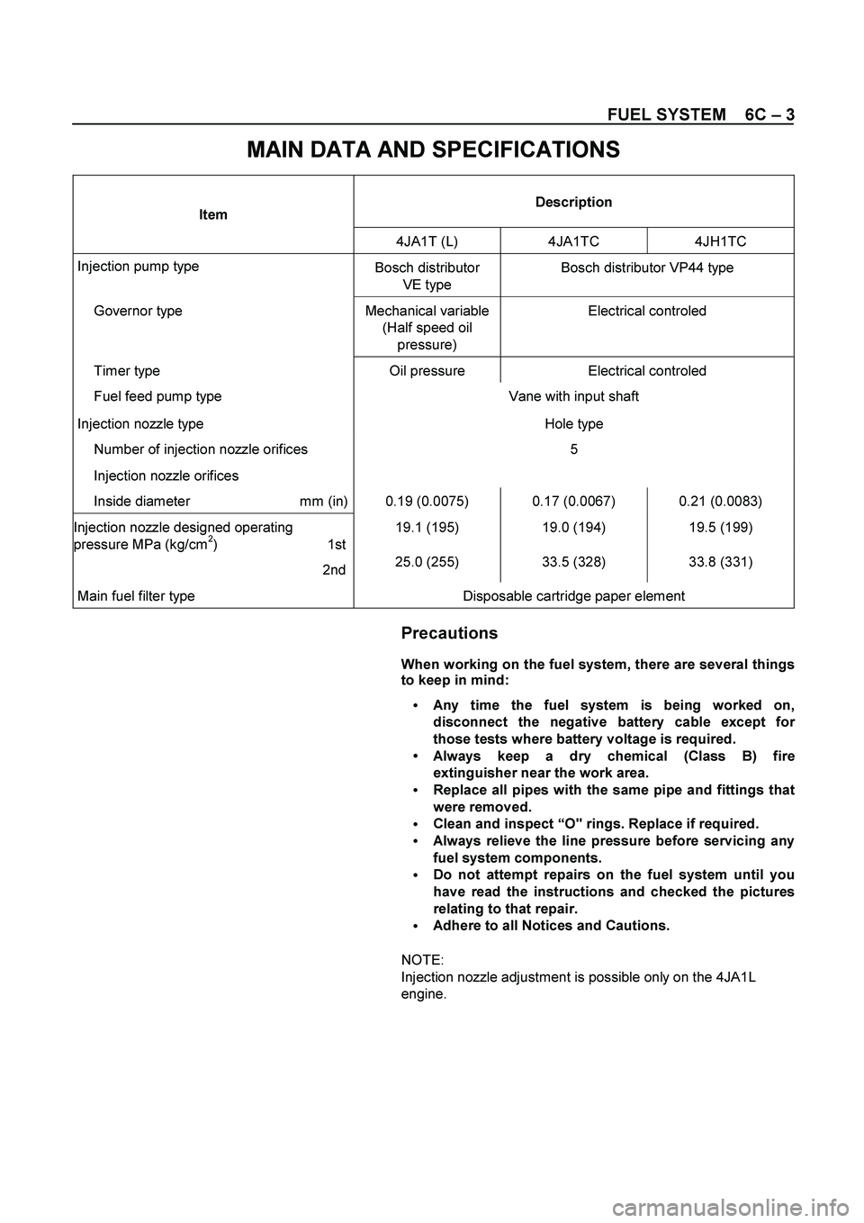
MAIN DATA AND SPECIFICATIONS
Description Item
4JA1T (L) 4JA1TC 4JH1TC
Injection pump type
Bosch distributor
VE type Bosch distributor VP44 type
Governor type Mechanical variable
(Half speed oil
pressure) Electrical controled
Timer type Oil pressure Electrical controled
Fuel feed pump type Vane with input shaft
Injection nozzle type Hole type
Number of injection nozzle orifices 5
Injection nozzle orifices
Inside diameter mm (in) 0.19 (0.0075) 0.17 (0.0067) 0.21 (0.0083)
19.1 (195) 19.0 (194) 19.5 (199) Injection nozzle designed operating
pressure MPa (kg/cm2) 1st
2nd 25.0 (255) 33.5 (328) 33.8 (331)
Main fuel filter type Disposable cartridge paper element
Precautions
When working on the fuel system, there are several things
to keep in mind:
Any time the fuel system is being worked on,
disconnect the negative battery cable except fo
r
those tests where battery voltage is required.
Always keep a dry chemical (Class B) fire
extinguisher near the work area.
Replace all pipes with the same pipe and fittings that
were removed.
Clean and inspect “O" rings. Replace if required.
Always relieve the line pressure before servicing any
fuel system components.
Do not attempt repairs on the fuel system until you
have read the instructions and checked the pictures
relating to that repair.
Adhere to all Notices and Cautions.
NOTE:
Injection nozzle adjustment is possible only on the 4JA1L
engine.
Page 1304 of 4264
6C – 4 FUEL SYSTEM
GENERAL DESCRIPTION
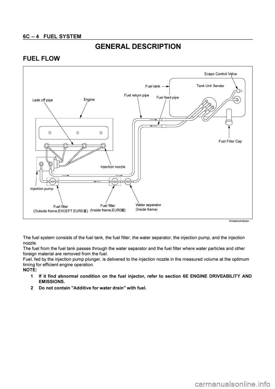
FUEL FLOW
RTW46CM F000201
The fuel system consists of the fuel tank, the fuel filter, the water separator, the injection pump, and the injection
nozzle.
The fuel from the fuel tank passes through the water separator and the fuel filter where water particles and other
foreign material are removed from the fuel.
Fuel, fed by the injection pump plunger, is delivered to the injection nozzle in the measured volume at the optimum
timing for efficient engine operation.
NOTE:
1 If it find abnormal condition on the fuel injector, refer to section 6E ENGINE DRIVEABILITY AND
EMISSIONS.
2 Do not contain "Additive for water drain" with fuel.
Page 1305 of 4264
FUEL SYSTEM 6C – 5
FUEL FILTER AND WATER SEPARATOR
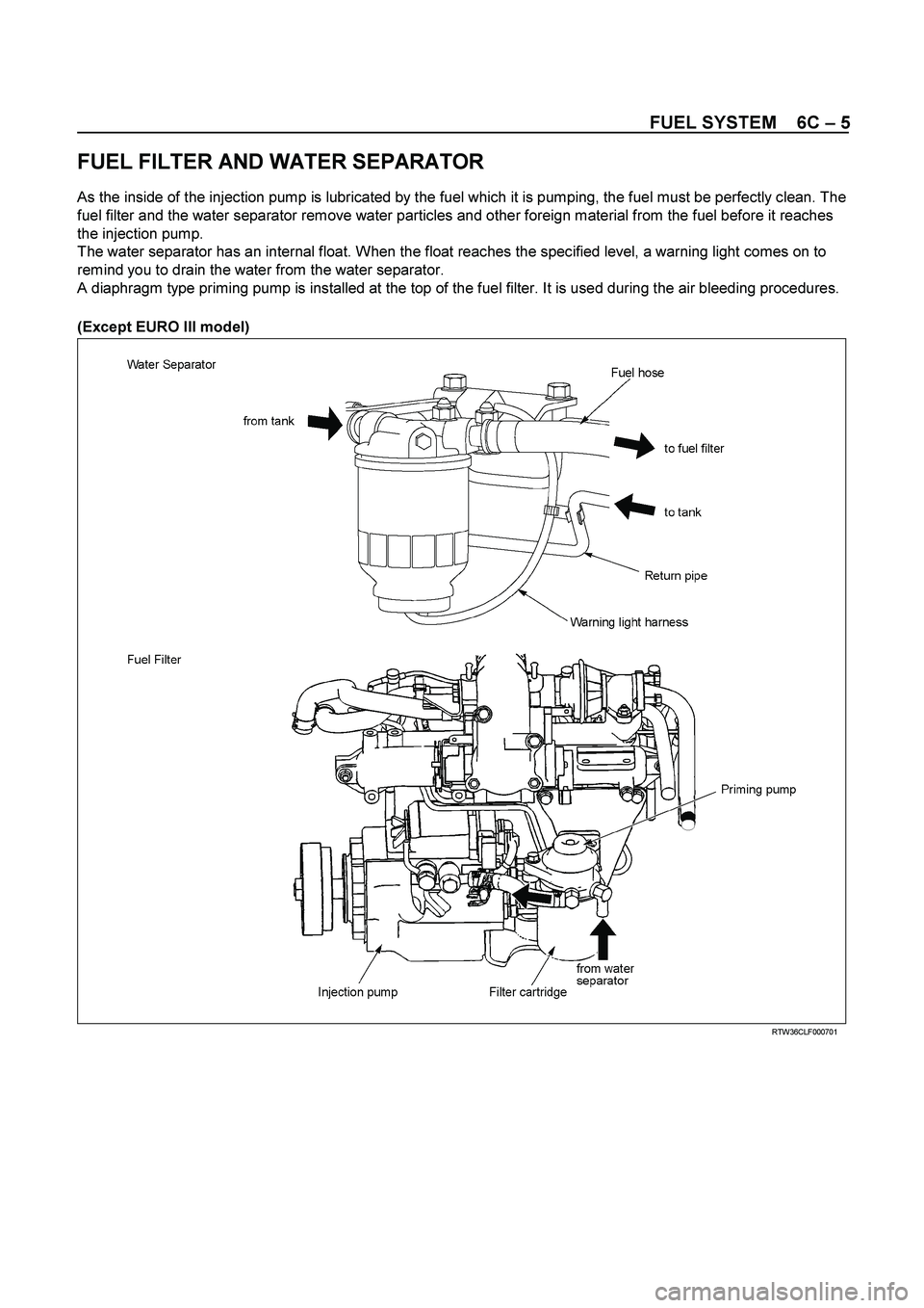
As the inside of the injection pump is lubricated by the fuel which it is pumping, the fuel must be perfectly clean. The
fuel filter and the water separator remove water particles and other foreign material from the fuel before it reaches
the injection pump.
The water separator has an internal float. When the float reaches the specified level, a warning light comes on to
remind you to drain the water from the water separator.
A diaphragm type priming pump is installed at the top of the fuel filter. It is used during the air bleeding procedures.
(Except EURO III model)
RTW36CLF000701