Page 1190 of 4264
6A – 50 ENGINE MECHANICAL
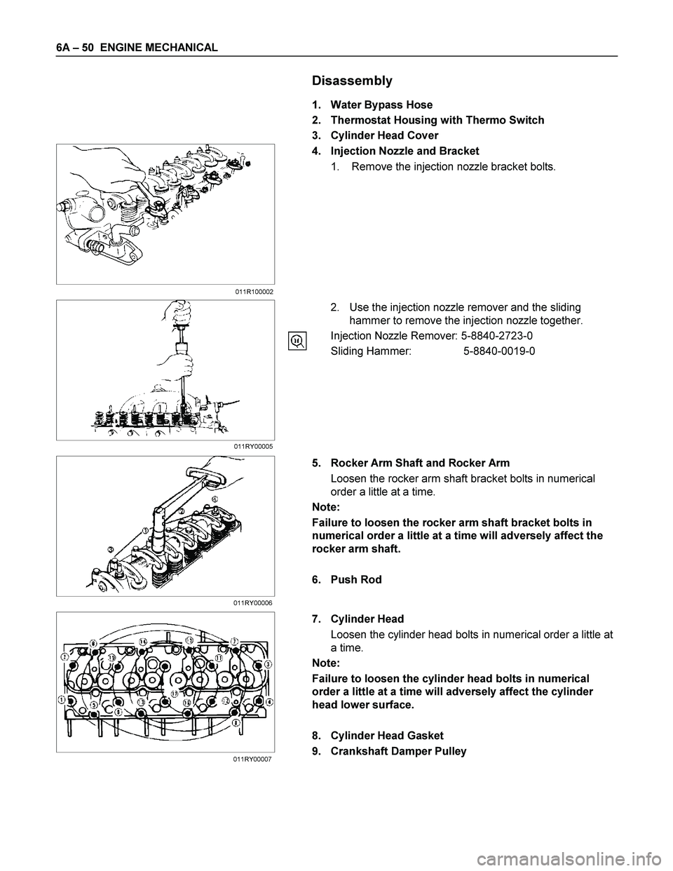
Disassembly
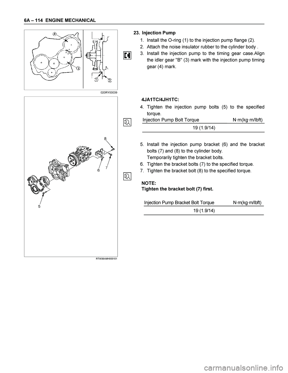
1. Water Bypass Hose
2. Thermostat Housing with Thermo Switch
3. Cylinder Head Cover
4. Injection Nozzle and Bracket
1. Remove the injection nozzle bracket bolts.
2. Use the injection nozzle remover and the sliding
hammer to remove the injection nozzle together.
Injection Nozzle Remover: 5-8840-2723-0
Sliding Hammer: 5-8840-0019-0
5. Rocker Arm Shaft and Rocker Arm
Loosen the rocker arm shaft bracket bolts in numerical
order a little at a time.
Note:
Failure to loosen the rocker arm shaft bracket bolts in
numerical order a little at a time will adversely affect the
rocker arm shaft.
6. Push Rod
7. Cylinder Head
Loosen the cylinder head bolts in numerical order a little at
a time.
Note:
Failure to loosen the cylinder head bolts in numerical
order a little at a time will adversely affect the cylinder
head lower surface.
8. Cylinder Head Gasket
9. Crankshaft Damper Pulley
011R100002
011RY00005
011RY00006
011RY00007
Page 1191 of 4264
ENGINE MECHANICAL 6A – 51
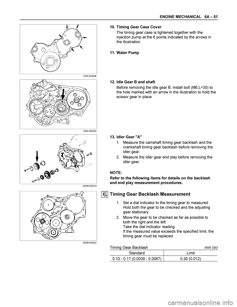
10. Timing Gear Case Cover
The timing gear case is tightened together with the
injection pump at the 6 points indicated by the arrows in
the illustration.
11. Water Pump
12. Idle Gear B and shaft
Before removing the idle gear B, install bolt (M6,L=30) to
the hole marked with an arrow in the illustration to hold the
scissor gear in place.
13. Idler Gear "A"
1. Measure the camshaft timing gear backlash and the
crankshaft timing gear backlash before removing the
idler gear.
2. Measure the idler gear end play before removing the
idler gear.
NOTE:
Refer to the following items for details on the backlash
and end play measurement procedures.
Timing Gear Backlash Measurement
1. Set a dial indicator to the timing gear to measured.
Hold both the gear to be checked and the adjusting
gear stationary.
2. Move the gear to be checked as far as possible to
both the right and the left.
Take the dial indicator reading.
If the measured value exceeds the specified limit, the
timing gear must be replaced.
Timing Gear Backlash mm (in)
Standard Limit
0.10 - 0.17 (0.0039 - 0.0067) 0.30 (0.012)
020L200006
020L200020
020RY00019
020RY00020
Page 1192 of 4264
6A – 52 ENGINE MECHANICAL
RTW36ASH000801
Idler Gear "A" End Play Measurement
Insert a feeler gauge between the idler gear and the thrust
collar to measure the gap and determine the idler gear
end play.
If the measured value exceeds the specified limit, the
thrust collar must be replaced.
Idler Gear End Play mm (in)
Standard Limit
0.07 (0.0028) 0.2 (0.0079)
4JA1T(L)
040R300009
14. Idle Gear Shaft
15. Crankshaft Timing Gear
4JA1TC/4JH1TC RTW36ASH001301
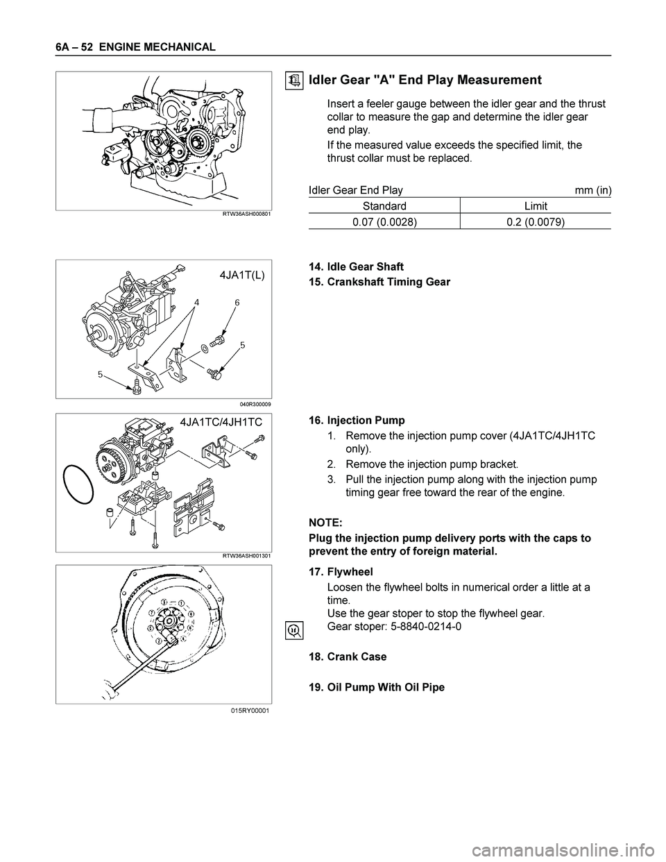
16. Injection Pump
1. Remove the injection pump cover (4JA1TC/4JH1TC
only).
2. Remove the injection pump bracket.
3. Pull the injection pump along with the injection pump
timing gear free toward the rear of the engine.
NOTE:
Plug the injection pump delivery ports with the caps to
prevent the entry of foreign material.
17. Flywheel
Loosen the flywheel bolts in numerical order a little at a
time.
Use the gear stoper to stop the flywheel gear.
Gear stoper: 5-8840-0214-0
18. Crank Case
19. Oil Pump With Oil Pipe
015RY00001
Page 1242 of 4264
6A – 102 ENGINE MECHANICAL
RTW46ALF000501
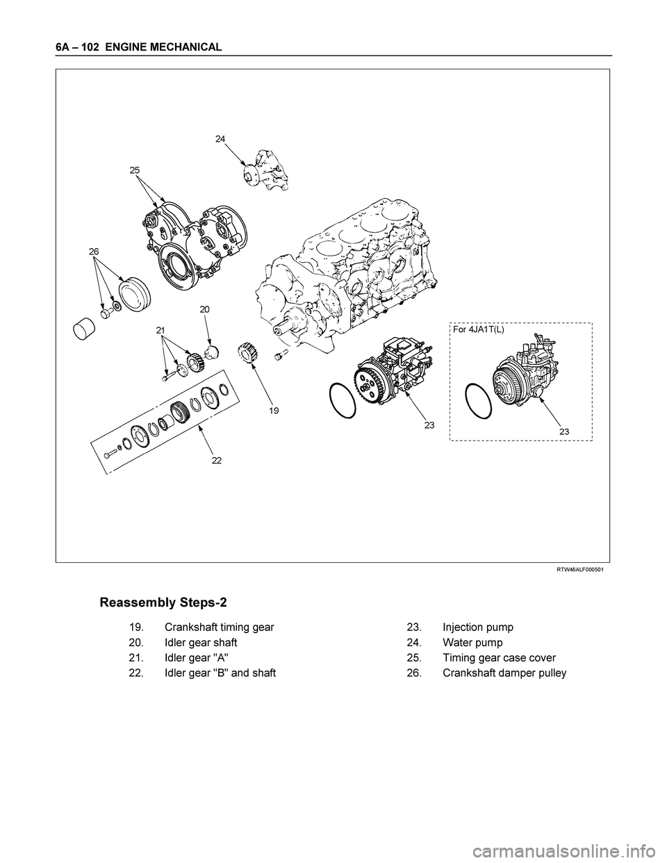
Reassembly Steps-2
19.
Crankshaft timing gear 23.
Injection pump
20.
Idler gear shaft 24.
Water pump
21.
Idler gear "A" 25.
Timing gear case cover
22.
Idler gear "B" and shaft 26.
Crankshaft damper pulley
Page 1243 of 4264
ENGINE MECHANICAL 6A – 103
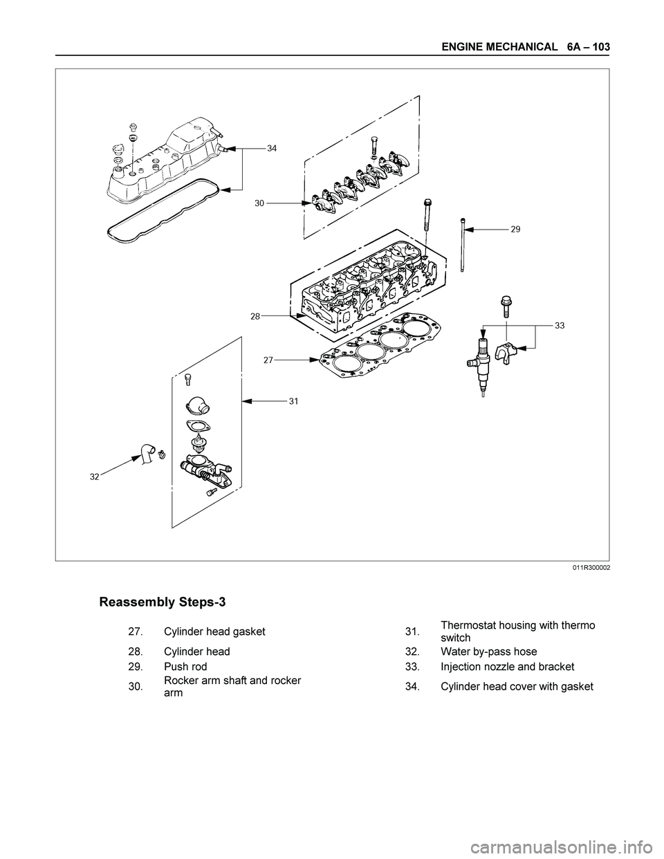
Reassembly Steps-3
27.
Cylinder head gasket 31. Thermostat housing with thermo
switch
28.
Cylinder head 32.
Water by-pass hose
29.
Push rod 33.
Injection nozzle and bracket
30. Rocker arm shaft and rocker
arm 34.
Cylinder head cover with gasket
011R300002
Page 1254 of 4264
6A – 114 ENGINE MECHANICAL
23. Injection Pump
1. Install the O-ring (1) to the injection pump flange (2).
2. Attach the noise insulator rubber to the cylinder body .
3. Install the injection pump to the timing gear case.Align
the idler gear "B" (3) mark with the injection pump timing
gear (4) mark.
RTW36AMH000101
4JA1TC/4JH1TC:
4. Tighten the injection pump bolts (5) to the specified
torque.
Injection Pump Bolt Torque N·m(kg·m/lbft)
19 (1.9/14)
5. Install the injection pump bracket (6) and the bracke
t
bolts (7) and (8) to the cylinder body.
Temporarily tighten the bracket bolts.
6. Tighten the bracket bolts (7) to the specified torque.
7. Tighten the bracket bolt (8) to the specified torque.
NOTE:
Tighten the bracket bolt (7) first.
Injection Pump Bracket Bolt Torque N·m(kg·m/lbft)
19 (1.9/14)
020RY00039
Page 1255 of 4264
ENGINE MECHANICAL 6A – 115
RTW46ASH002201
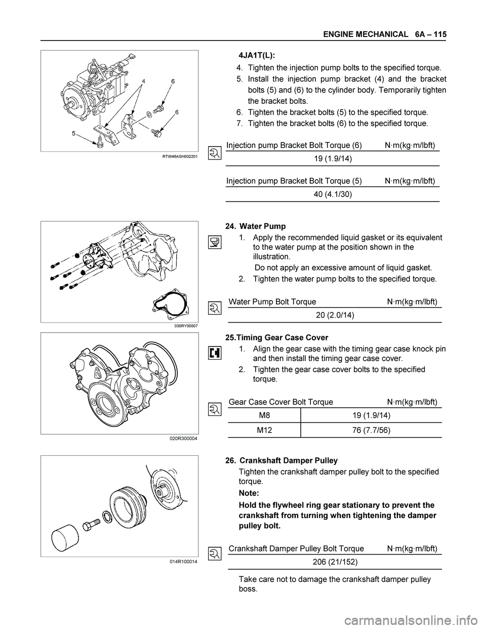
4JA1T(L):
4. Tighten the injection pump bolts to the specified torque.
5. Install the injection pump bracket (4) and the bracke
t
bolts (5) and (6) to the cylinder body. Temporarily tighten
the bracket bolts.
6. Tighten the bracket bolts (5) to the specified torque.
7. Tighten the bracket bolts (6) to the specified torque.
Injection pump Bracket Bolt Torque (6) N·m(kg·m/lbft)
19 (1.9/14)
Injection pump Bracket Bolt Torque (5) N·m(kg·m/lbft)
40 (4.1/30)
030RY00007
24. Water Pump
1. Apply the recommended liquid gasket or its equivalent
to the water pump at the position shown in the
illustration.
Do not apply an excessive amount of liquid gasket.
2. Tighten the water pump bolts to the specified torque.
Water Pump Bolt Torque N·m(kg·m/lbft)
20 (2.0/14)
25.Timing Gear Case Cover
1.
Align the gear case with the timing gear case knock pin
and then install the timing gear case cover.
2. Tighten the gear case cover bolts to the specified
torque.
Gear Case Cover Bolt Torque N·m(kg·m/lbft)
M8 19 (1.9/14)
M12 76 (7.7/56)
26. Crankshaft Damper Pulley
Tighten the crankshaft damper pulley bolt to the specified
torque.
Note:
Hold the flywheel ring gear stationary to prevent the
crankshaft from turning when tightening the damper
pulley bolt.
Crankshaft Damper Pulley Bolt Torque N·m(kg·m/lbft)
206 (21/152)
Take care not to damage the crankshaft damper pulley
boss.
014R100014 020R300004
Page 1257 of 4264
ENGINE MECHANICAL 6A – 117
RTW46ASH001201
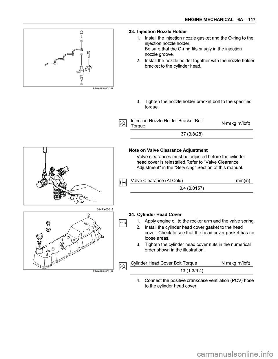
33. Injection Nozzle Holder
1. Install the injection nozzle gasket and the O-ring to the
injection nozzle holder.
Be sure that the O-ring fits snugly in the injection
nozzle groove.
2. Install the nozzle holder toghther with the nozzle holder
bracket to the cylinder head.
3. Tighten the nozzle holder bracket bolt to the specified
torque.
Injection Nozzle Holder Bracket Bolt
Torque N·m(kg·m/lbft)
37 (3.8/28)
Note on Valve Clearance Adjustment
Valve clearances must be adjusted before the cylinder
head cover is reinstalled.Refer to "Valve Clearance
Adjustment" in the "Servicing" Section of this manual.
Valve Clearance (At Cold) mm(in)
0.4 (0.0157)
RTW46ASH001101
34. Cylinder Head Cover
1. Apply engine oil to the rocker arm and the valve spring.
2. Install the cylinder head cover gasket to the head
cover. Check to see that the head cover gasket has no
loose areas.
3. Tighten the cylinder head cover nuts in the numerical
order shown in the illustration.
Cylinder Head Cover Bolt Torque N·m(kg·m/lbft)
13 (1.3/9.4)
4. Connect the positive crankcase ventilation (PCV) hose
to the cylinder head cover.
014RY00015