Page 1176 of 4264
6A – 36 ENGINE MECHANICAL
GENERAL DESCRIPTION
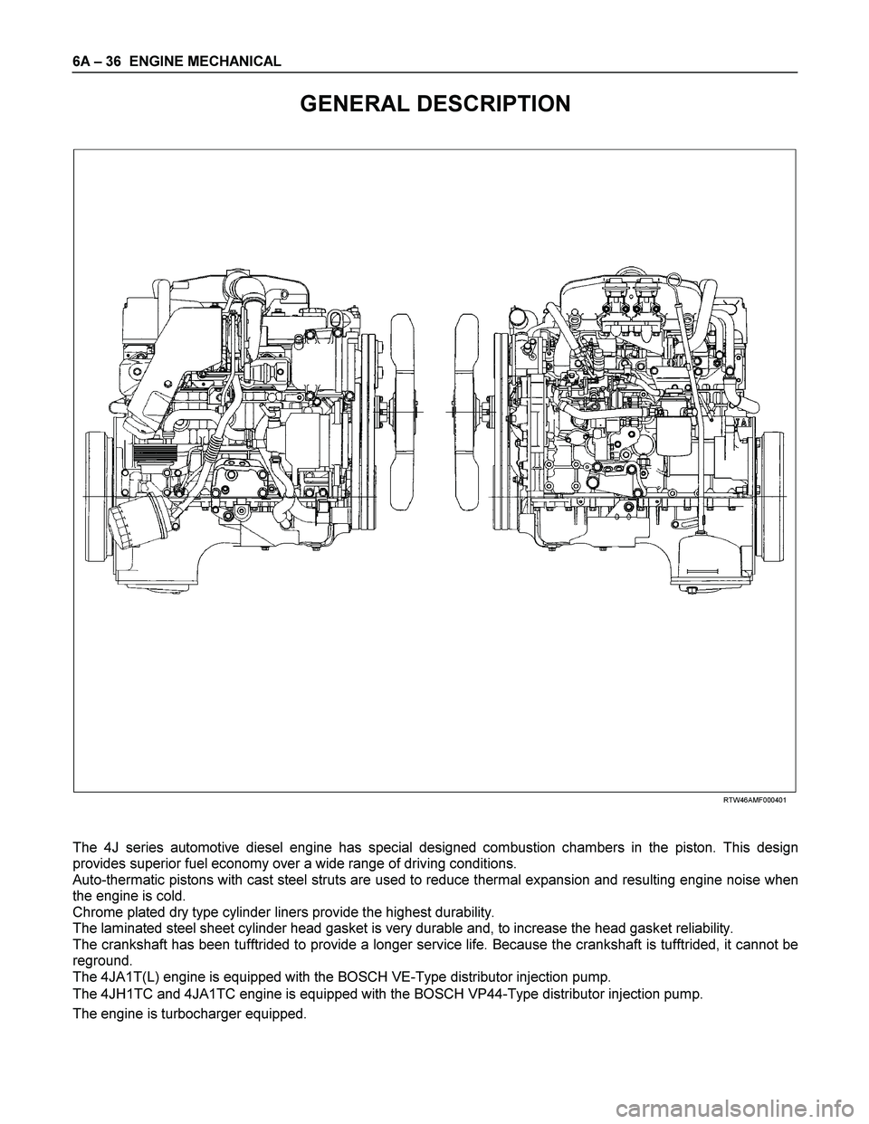
RTW46AMF000401
The 4J series automotive diesel engine has special designed combustion chambers in the piston. This design
provides superior fuel economy over a wide range of driving conditions.
Auto-thermatic pistons with cast steel struts are used to reduce thermal expansion and resulting engine noise when
the engine is cold.
Chrome plated dry type cylinder liners provide the highest durability.
The laminated steel sheet cylinder head gasket is very durable and, to increase the head gasket reliability.
The crankshaft has been tufftrided to provide a longer service life. Because the crankshaft is tufftrided, it cannot be
reground.
The 4JA1T(L) engine is equipped with the BOSCH VE-Type distributor injection pump.
The 4JH1TC and 4JA1TC engine is equipped with the BOSCH VP44-Type distributor injection pump.
The engine is turbocharger equipped.
Page 1179 of 4264
ENGINE MECHANICAL 6A – 39
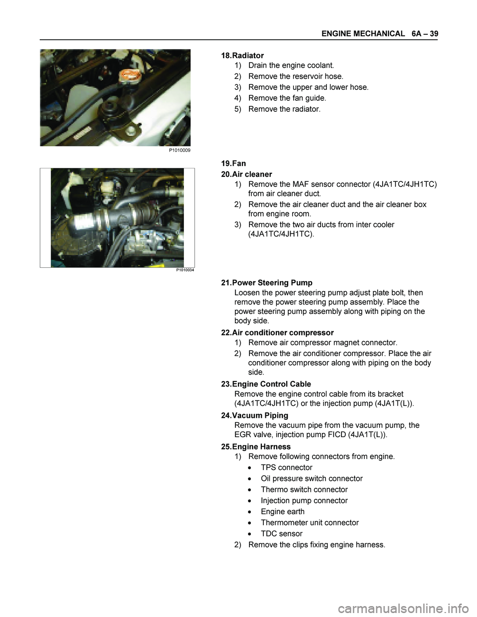
18. Radiator
1) Drain the engine coolant.
2) Remove the reservoir hose.
3) Remove the upper and lower hose.
4) Remove the fan guide.
5) Remove the radiator.
19. Fan
P1010034
20. Air cleaner
1) Remove the MAF sensor connector (4JA1TC/4JH1TC) from air cleaner duct.
2) Remove the air cleaner duct and the air cleaner box from engine room.
3) Remove the two air ducts from inter cooler (4JA1TC/4JH1TC).
21. Power Steering Pump Loosen the power steering pump adjust plate bolt, then
remove the power steering pump assembly. Place the
power steering pump assembly along with piping on the
body side.
22. Air conditioner compressor 1) Remove air compressor magnet connector.
2) Remove the air conditioner compressor. Place the air conditioner compressor along with piping on the body
side.
23. Engine Control Cable Remove the engine control cable from its bracket
(4JA1TC/4JH1TC) or the injection pump (4JA1T(L)).
24. Vacuum Piping Remove the vacuum pipe from the vacuum pump, the
EGR valve, injection pump FICD (4JA1T(L)).
25. Engine Harness 1) Remove following connectors from engine.
� TPS connector
� Oil pressure switch connector
� Thermo switch connector
� Injection pump connector
� Engine earth
� Thermometer unit connector
� TDC sensor
2) Remove the clips fixing engine harness.
P1010009
Page 1180 of 4264
6A – 40 ENGINE MECHANICAL
140R300001
26. Fuel Hose
Remove the fuel hose from the fuel filter (Except EURO
III).
RTW46ASH000501
Remove the fuel hose from injection pump (EURO III
only).
27. Exhaust Pipe
Remove the front exhaust pipe bolts and separate the
exhaust manifold and the front exhaust pipe.
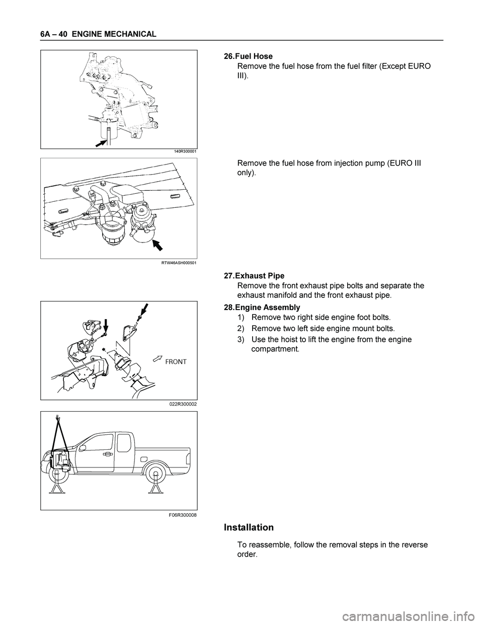
28. Engine Assembly
1) Remove two right side engine foot bolts.
2) Remove two left side engine mount bolts.
3) Use the hoist to lift the engine from the engine
compartment.
Installation
To reassemble, follow the removal steps in the reverse
order.
022R300002
F06R300008
Page 1183 of 4264
ENGINE MECHANICAL 6A – 43
ENGINE OVERHAUL
REMOVAL
EXTERNAL PARTS
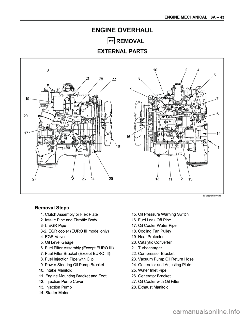
RTW36AMF000401
Removal Steps
1. Clutch Assembly or Flex Plate
2. Intake Pipe and Throttle Body
3-1. EGR Pipe
3-2. EGR cooler (EURO III model only)
4. EGR Valve
5. Oil Level Gauge
6. Fuel Filter Assembly (Except EURO III)
7. Fuel Filter Bracket (Except EURO III)
8. Fuel Injection Pipe with Clip
9. Power Steering Oil Pump Bracket
10. Intake Manifold
11. Engine Mounting Bracket and Foot
12. Injection Pump Cover
13. Injection Pump
14. Starter Motor
15. Oil Pressure Warning Switch
16. Fuel Leak Off Pipe
17. Oil Cooler Water Pipe
18. Cooling Fan Pulley
19. Heat Protector
20. Catalytic Converter
21. Turbocharger
22. Compressor Bracket
23. Vacuum Pump Oil Return Hose
24. Generator and Adjusting Plate
25. Water Inlet Pipe
26. Generator Bracket
27. Oil Cooler with Oil Filter
28. Exhaust Manifold
Page 1185 of 4264
ENGINE MECHANICAL 6A – 45
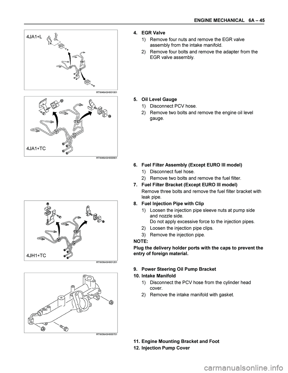
4JA1�L
RTW46ASH001001
4. EGR Valve
1) Remove four nuts and remove the EGR valve
assembly from the intake manifold.
2) Remove four bolts and remove the adapter from the
EGR valve assembly.
4JA1�TC RTW46ASH000901
5. Oil Level Gauge
1) Disconnect PCV hose.
2) Remove two bolts and remove the engine oil level
gauge.
6. Fuel Filter Assembly (Except EURO III model)
1) Disconnect fuel hose.
2) Remove two bolts and remove the fuel filter.
7. Fuel Filter Bracket (Except EURO III model)
Remove three bolts and remove the fuel filter bracket with
leak pipe.
4JH1�TC RTW36ASH001201
8. Fuel Injection Pipe with Clip
1) Loosen the injection pipe sleeve nuts at pump side
and nozzle side.
Do not apply excessive force to the injection pipes.
2) Loosen the injection pipe clips.
3) Remove the injection pipe.
NOTE:
Plug the delivery holder ports with the caps to prevent the
entry of foreign material.
9. Power Steering Oil Pump Bracket
RTW36ASH000701
10. Intake Manifold
1) Disconnect the PCV hose from the cylinder head
cover.
2) Remove the intake manifold with gasket.
11. Engine Mounting Bracket and Foot
12. Injection Pump Cover
Page 1186 of 4264
6A – 46 ENGINE MECHANICAL
13. Injection Pump
Rrefer to secton 6C-19 (Injection Iump)
14. Starter Motor
15. Oil Pressure Warning Switch
16. Fuel Leak Off Pipe
17. Oil Cooler Water Pipe
18. Cooling Fan Pulley
19. Heat Protector
20. Catalytic Converter
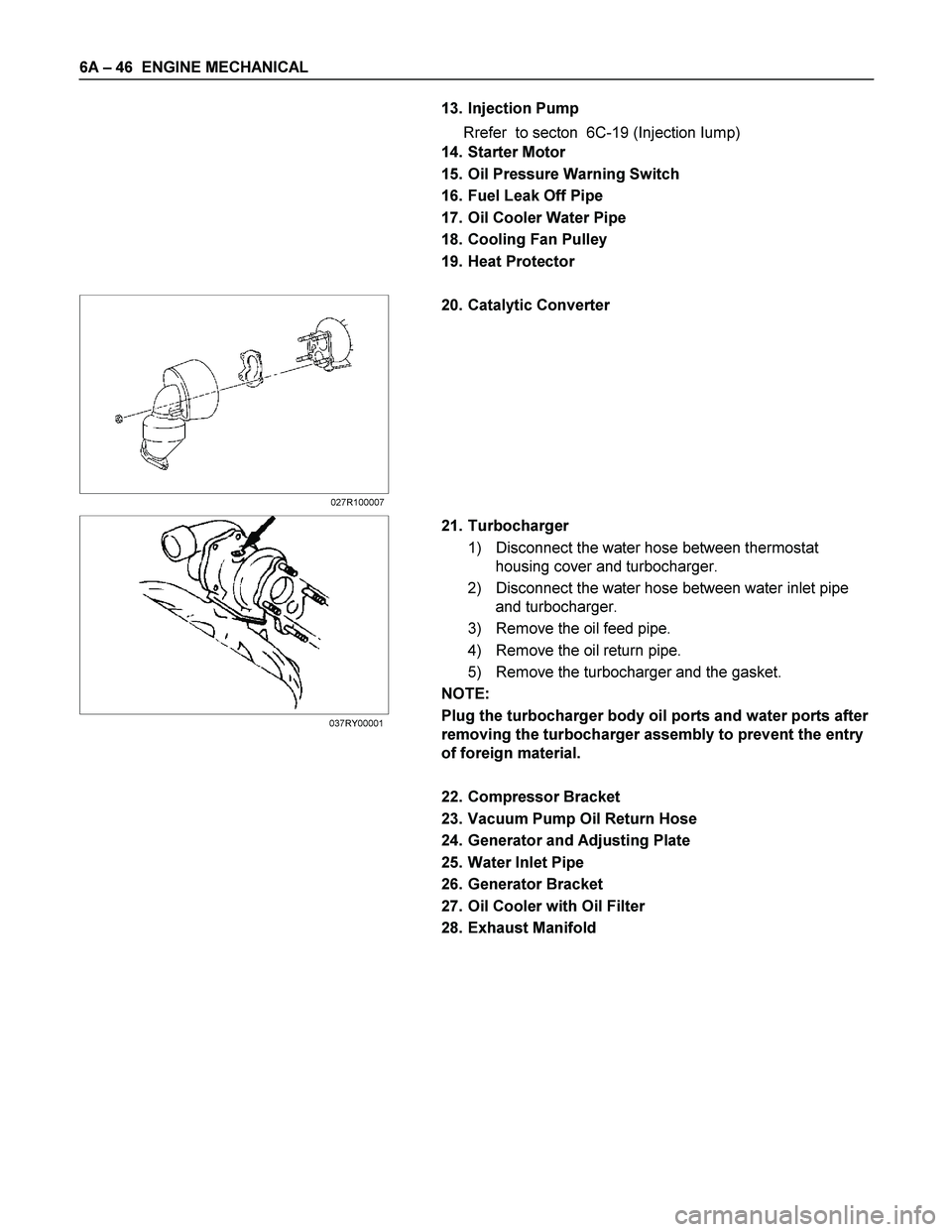
21. Turbocharger
1) Disconnect the water hose between thermostat
housing cover and turbocharger.
2) Disconnect the water hose between water inlet pipe
and turbocharger.
3) Remove the oil feed pipe.
4) Remove the oil return pipe.
5) Remove the turbocharger and the gasket.
NOTE:
Plug the turbocharger body oil ports and water ports after
removing the turbocharger assembly to prevent the entry
of foreign material.
22. Compressor Bracket
23. Vacuum Pump Oil Return Hose
24. Generator and Adjusting Plate
25. Water Inlet Pipe
26. Generator Bracket
27. Oil Cooler with Oil Filter
28. Exhaust Manifold
027R100007
037RY00001
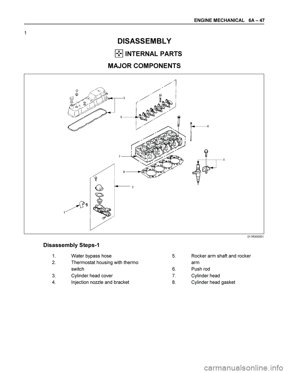
Page 1187 of 4264
ENGINE MECHANICAL 6A – 47
1
DISASSEMBLY
INTERNAL PARTS
MAJOR COMPONENTS
Disassembly Steps-1
1.
Water bypass hose 5.
Rocker arm shaft and rocker
2.
Thermostat housing with thermo arm
switch 6. Push rod
3.
Cylinder head cover 7.
Cylinder head
4.
Injection nozzle and bracket 8.
Cylinder head gasket
011R300001
Page 1188 of 4264
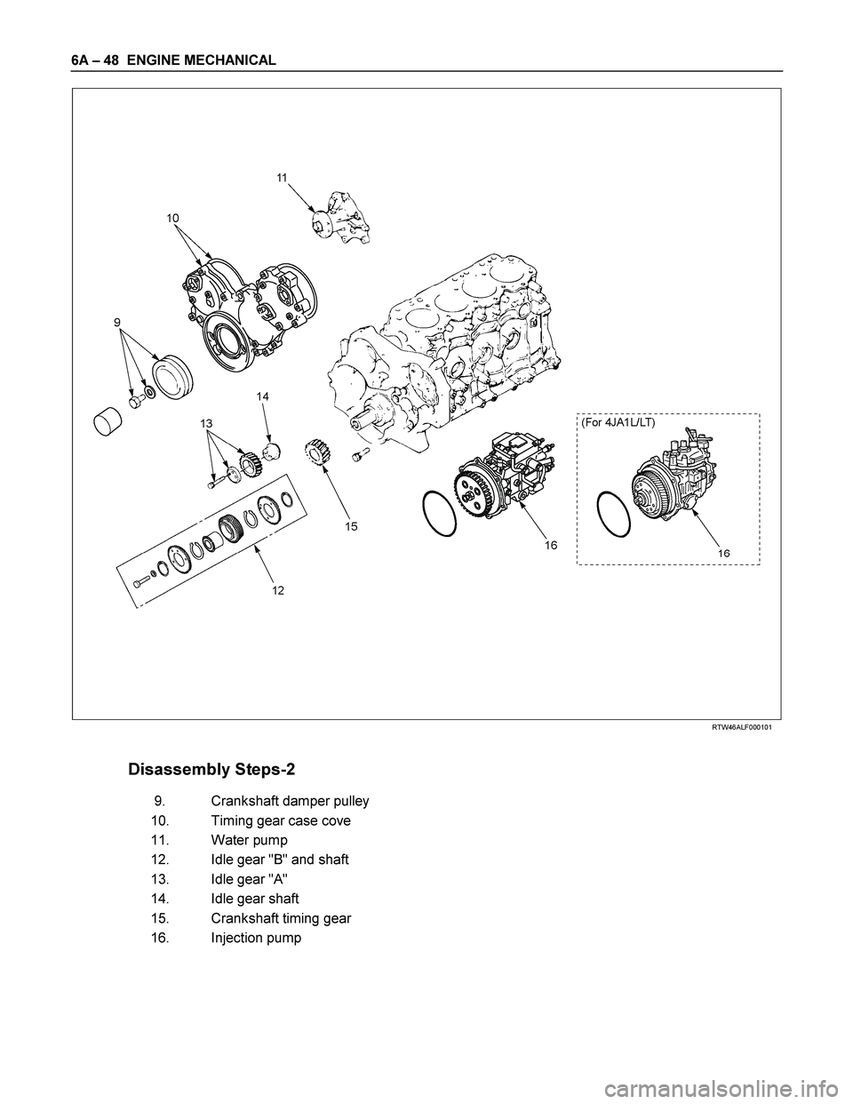
6A – 48 ENGINE MECHANICAL
RTW46ALF000101
Disassembly Steps-2
9. Crankshaft damper pulley
10. Timing gear case cove
11. Water pump
12. Idle gear "B" and shaft
13. Idle gear "A"
14. Idle gear shaft
15. Crankshaft timing gear
16. Injection pump