Page 2457 of 4264
ENGINE MECHANICAL (C24SE) 6A-37
Hydraulic Valve Lifters, Replace
Removal
1. Remove the spark plug connectors and spark plugs.
2. Remove the camshaft housing cover.
Removal
3. Turn the crankshaft at fastening bolt of toothed belt drive
gear in the direction of the engine rotation until the cam
of hydraulic valve lifter being replaced stands vertically.
Removal
4. Apply 5-8840-0457-0 to the camshaft housing, valve
spring cap and tension valve spring.
Removal
5. Remove the cam follower from camshaft housing.
Note thrust pieces.
6. Remove hydraulic valve lifter from camshaft housing.
Camshaft Housing, Replace
Removal
Cylinder head-see operation “Cylinder Head. Remove and
Install”.
Page 2459 of 4264
ENGINE MECHANICAL (C24SE) 6A-39
Camshaft Housing, Check for Plane Surface
Clean
Sealing surfaces.
Inspection
Check length and width of sealing surface for deformation and
diagnosis for warpage and use straight edge feeler gauge.
Measure
Height of camshaft housing (sealing surface to sealing
surface).
Dimension I: (74.0 mm)
Cylinder Head, Removal and Installation
Important
Only remove cylinder head with engine cold (room
temperature).
Removal
1. Remove the alternator, power steering and V-belts.
Removal
2. Loosen the fastening bolts from alternator.
3. Loosen the lower alternator fastening bolt by swinging
the alternator to the rear.
Removal
4. Remove the front toothed belt cover.
5. Remove the toothed belt from camshaft pulley.
See operation "Timing Check and Adjust".
Page 2460 of 4264
6A-40 ENGINE MECHANICAL (C24SE)
Removal
6. Remove the camshaft housing cover and camshaft
pulley by counter-holding at the hex head of camshaft.
Removal
7. Remove the fastening bolts from camshaft housing.
Removal
8. Remove the exhaust pipe from exhaust manifold.
9. Loosen the cylinder head bolts spirally from the outside
inwards (first 1/4, then 1/2 revolution).
Removal
1. Remove the camshaft housing from cylinder head.
2. Remove the cam followers, thrust pieces and hydraulic
valve lifters.
Note the allocation.
3. Remove the cylinder head.
Clean
Sealing surfaces, bores and threads of cylinder head bolts.
Inspection
Check cylinder head and cylinder block for plane surfface-see
operations “Cylinder Head, Check for Plane Surface” and
“Cylinder Block, Check for Plane Surface.”
Page 2462 of 4264
6A-42 ENGINE MECHANICAL (C24SE)
Installation
1. Install the fastening bolts.
2. Loosen the lower alternator fastening bolt.
3. Install the alternator, power steering and V-belts.
Cylinder Head, Disassemble and Assemble
Removal
1. Remove the hydraulic valve lifters.
Lay aside in installation positions.
2. Remove the spark plugs, exhaust manifold and intake
manifold from cylinder head.
Removal
1. Mark valves.
2. Remove the tension valve springs with 5-8840-2594-0
(1).
3. Remove valve keepers, valve spring cap and valve
spring.
Removal
1. Remove the valve and valve stem seal.
2. Remove the valve spacer ring (1-exhaust) and valve
spring seat (2-intake).
3. Remove valve from cylinder head.
Clean
Sealing surfaces.
Page 2466 of 4264
6A-46 ENGINE MECHANICAL (C24SE)
Inspection
Check contact pattern (I
) on valve seat and in cylinder head.
Clean
Valves, valve guides, cylinder head.
Flywheel
Removal
1. Remove transmission and clutch.
2. Remove flywheel while locking with 5-88400-446-0.
Torque - Angle Method
Flywheel to crankshaft - 65 Nm/6.5 kgf�
m.+30�
to 45�
Important!
Use new bolts.
Do not apply grease to the thread.
Installation
1. Install clutch and transmission.
Component Parts
Flywheel and Ring gear. (Manual Transmission)
Page 2471 of 4264
ENGINE MECHANICAL (C24SE) 6A-51
OPERATIONS ON CRANK DRIVE
Con-Rod Bearing
Removal
1. Remove oil pan and bearing bridge according to the corresponding operation.
2. Remove con-rod bearing cap and con-rod bearing after marking both sides.
Clean
Con-rod journal, con-rod bearing cap
Installation
1. Install new bearing shafts lightly coated with engine oil.
2. Install con-rod bearing cap.
Torque-Angle Method
Con-rod bearing cap to con-rod - 35N �
m (3.5 kgf �
m) +45 �
to
60 �
Important!
Use new bolts.
3. Install oil pan and bearing bridge according to the corresponding operation.
Piston with Con-Rod
Removal
1. Remove cylinder head and oil pan according to the corresponding operations.
2. Remove piston with con-rod after marking con-rod bearing cap.
Inspection
Remove and install all parts, if applicable.
Important!
Ring gap offset:
Piston rings - 180 �
.
Oil scraper rings - 25 to 50 mm/1 to 2 in. from gap of
intermediate ring to the left and to the right.
Page 2472 of 4264

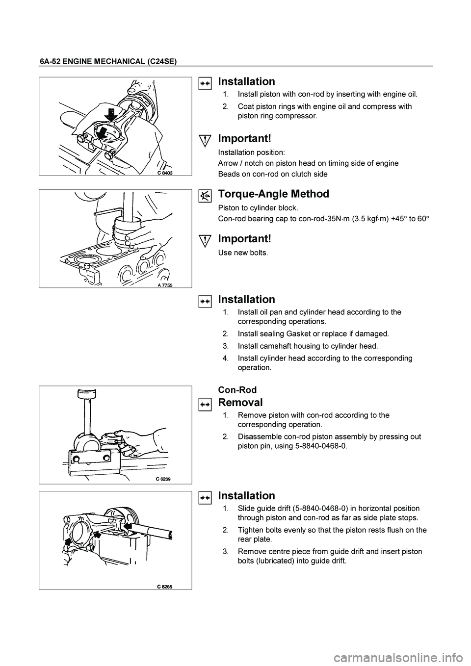
6A-52 ENGINE MECHANICAL (C24SE)
Installation
1. Install piston with con-rod by inserting with engine oil.
2. Coat piston rings with engine oil and compress with
piston ring compressor.
Important!
Installation position:
Arrow / notch on piston head on timing side of engine
Beads on con-rod on clutch side
Torque-Angle Method
Piston to cylinder block.
Con-rod bearing cap to con-rod-35N�m (3.5 kgf�m) +45� to 60�
Important!
Use new bolts.
Installation
1. Install oil pan and cylinder head according to the
corresponding operations.
2. Install sealing Gasket or replace if damaged.
3. Install camshaft housing to cylinder head.
4. Install cylinder head according to the corresponding
operation.
Con-Rod
Removal
1. Remove piston with con-rod according to the
corresponding operation.
2. Disassemble con-rod piston assembly by pressing out
piston pin, using 5-8840-0468-0.
Installation
1. Slide guide drift (5-8840-0468-0) in horizontal position
through piston and con-rod as far as side plate stops.
2. Tighten bolts evenly so that the piston rests flush on the
rear plate.
3. Remove centre piece from guide drift and insert piston
bolts (lubricated) into guide drift.
Page 2481 of 4264
ENGINE MECHANICAL (C24SE) 6A-61
OPERATIONS ON OIL CIRCULATION
Cylinder Head Safety Valve
Removal
1. Remove cylinder head according to the corresponding
operation.
2. Make hole in core plugs with pointed drift, turn in self
tapping screw and edge out.
Important!
Cover oil duct in cylinder head with piece of cloth.
3. Pull out valve retainer, using commercially available tool.
4. Remove ball and spring.
5. Cut three threads in the ball seating with M 10 tap (3rd
stage).
6. Coat tap with grease.
7. Remove ball seating from cylinder head with
commercially available tool.
Do not damage cylinder head.