2004 ISUZU TF SERIES fuse
[x] Cancel search: fusePage 659 of 4264
ELECTRICAL-BODY AND CHASSIS 8A-1
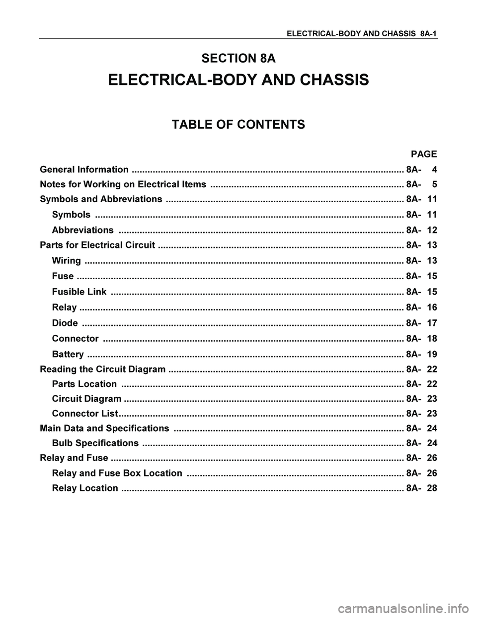
SECTION 8A
ELECTRICAL-BODY AND CHASSIS
TABLE OF CONTENTS
PAGE
General Information ........................................................................................................ 8A- 4
Notes for Working on Electrical Items .......................................................................... 8A- 5
Symbols and Abbreviations ........................................................................................... 8A- 11
Symbols ...................................................................................................................... 8A- 11
Abbreviations ............................................................................................................. 8A- 12
Parts for Electrical Circuit .............................................................................................. 8A- 13
Wiring .......................................................................................................................... 8A- 13
Fuse ............................................................................................................................. 8A- 15
Fusible Link ................................................................................................................ 8A- 15
Relay ............................................................................................................................ 8A- 16
Diode ........................................................................................................................... 8A- 17
Connector ................................................................................................................... 8A- 18
Battery ......................................................................................................................... 8A- 19
Reading the Circuit Diagram .......................................................................................... 8A- 22
Parts Location ............................................................................................................ 8A- 22
Circuit Diagram ........................................................................................................... 8A- 23
Connector List ............................................................................................................. 8A- 23
Main Data and Specifications ........................................................................................ 8A- 24
Bulb Specifications .................................................................................................... 8A- 24
Relay and Fuse ................................................................................................................ 8A- 26
Relay and Fuse Box Location ................................................................................... 8A- 26
Relay Location ............................................................................................................ 8A- 28
Page 660 of 4264
8A-2 ELECTRICAL-BODY AND CHASSIS
PAGE
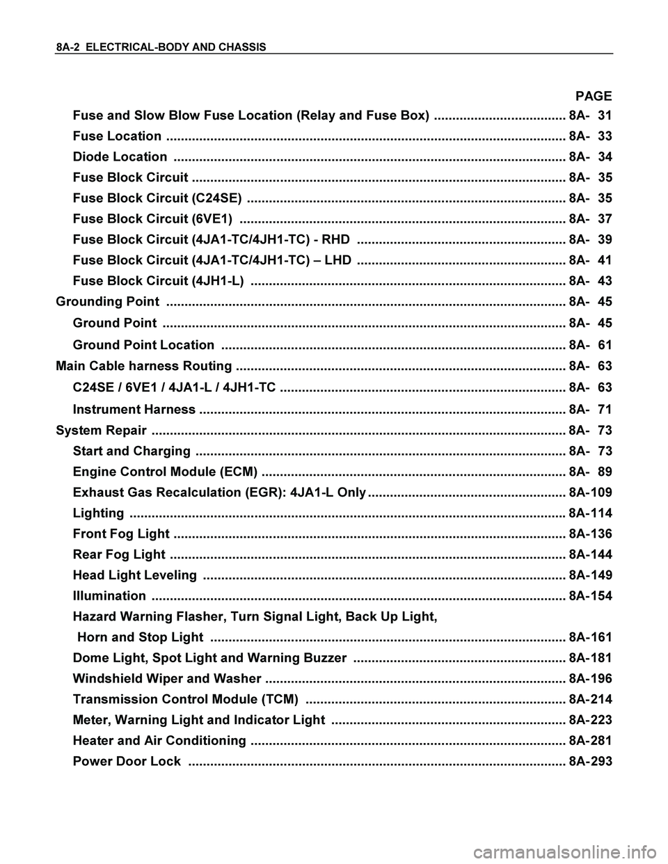
Fuse and Slow Blow Fuse Location (Relay and Fuse Box) .................................... 8A- 31
Fuse Location ............................................................................................................. 8A- 33
Diode Location ........................................................................................................... 8A- 34
Fuse Block Circuit ...................................................................................................... 8A- 35
Fuse Block Circuit (C24SE) ....................................................................................... 8A- 35
Fuse Block Circuit (6VE1) ......................................................................................... 8A- 37
Fuse Block Circuit (4JA1-TC/4JH1-TC) - RHD ......................................................... 8A- 39
Fuse Block Circuit (4JA1-TC/4JH1-TC) – LHD ......................................................... 8A- 41
Fuse Block Circuit (4JH1-L) ...................................................................................... 8A- 43
Grounding Point ............................................................................................................. 8A- 45
Ground Point .............................................................................................................. 8A- 45
Ground Point Location .............................................................................................. 8A- 61
Main Cable harness Routing .......................................................................................... 8A- 63
C24SE / 6VE1 / 4JA1-L / 4JH1-TC .............................................................................. 8A- 63
Instrument Harness .................................................................................................... 8A- 71
System Repair .................................................................................................................8A- 73
Start and Charging ..................................................................................................... 8A- 73
Engine Control Module (ECM) ................................................................................... 8A- 89
Exhaust Gas Recalculation (EGR): 4JA1-L Only ...................................................... 8A- 109
Lighting ....................................................................................................................... 8A- 114
Front Fog Light ........................................................................................................... 8A- 136
Rear Fog Light ............................................................................................................ 8A- 144
Head Light Leveling ................................................................................................... 8A- 149
Illumination ................................................................................................................. 8A- 154
Hazard Warning Flasher, Turn Signal Light, Back Up Light,
Horn and Stop Light ................................................................................................. 8A- 161
Dome Light, Spot Light and Warning Buzzer .......................................................... 8A- 181
Windshield Wiper and Washer .................................................................................. 8A- 196
Transmission Control Module (TCM) ....................................................................... 8A- 214
Meter, Warning Light and Indicator Light ................................................................ 8A- 223
Heater and Air Conditioning ...................................................................................... 8A- 281
Power Door Lock ....................................................................................................... 8A- 293
Page 662 of 4264
8A-4 ELECTRICAL-BODY AND CHASSIS
GENERAL INFORMATION
The body and chassis electrical system operates on a twelve volt power supply with negative ground polarity.
The main harness consists of the engine harness, the instrument harness, the body harness, and the chassis
harness.
The harnesses use a split corrugated tube to protect the wires from the elements.
Wire size is determined by current flow, circuit length, and voltage drop.
All wires have color-coded insulation.
Wire color-codes are shown in the circuit diagrams.
This makes it easier to trace circuits and to make the proper connections.
Each circuit consists of the following:
1. Power source - The battery and the alternator
2. Wires - To carry electrical current through the circuit
3. Fuses - To protect the circuit against current overload
4. Relays - To protect voltage drop between the battery and the circuit parts and to protect the switch points against
burning
5. Switches - To open and close the circuit
6. Load - Any device, such as a light or motor, which converts the electrical current into useful work
7. Ground - To allow the current to flow back to the power source
Page 665 of 4264

ELECTRICAL-BODY AND CHASSIS 8A-7
Pin Tang Lock Type
1. Insert a slender shaft 3 into the connector housing open
end
4.
2. Push the tang lock
8flat (toward the wire side of the
connector).
Pull the wire
6 with pin 7free from the wire side of the
connector.
Connector Pin Insertion
1. Check that the tang lock 8 is fully up.
2. Insert the pin
7 from the connector wire side 9.
Push the pin in until the tang lock closes firmly.
3. Gently pull on the wires
6to make sure that connector pin
is firmly set in place.
Fuse Replacement
The replacement fuse must have the same amperage
specification as the original fuse.
Never replace a burn out fuse with a fuse of a different
amperage specification.
Doing so can result in an electrical fire or other serious circuit
damage.
Parts Handling
Be careful for parts handling and any part should not be
dropped or thrown, otherwise short circuit or disorder may
result.
Wiring Harness
1. When assembling the parts, be careful not to bite or wedge
the wiring harness.
2. All electrical connections must be kept clean and tight.
Page 669 of 4264
ELECTRICAL-BODY AND CHASSIS 8A-11
SYMBOLS AND ABBREVIATIONS
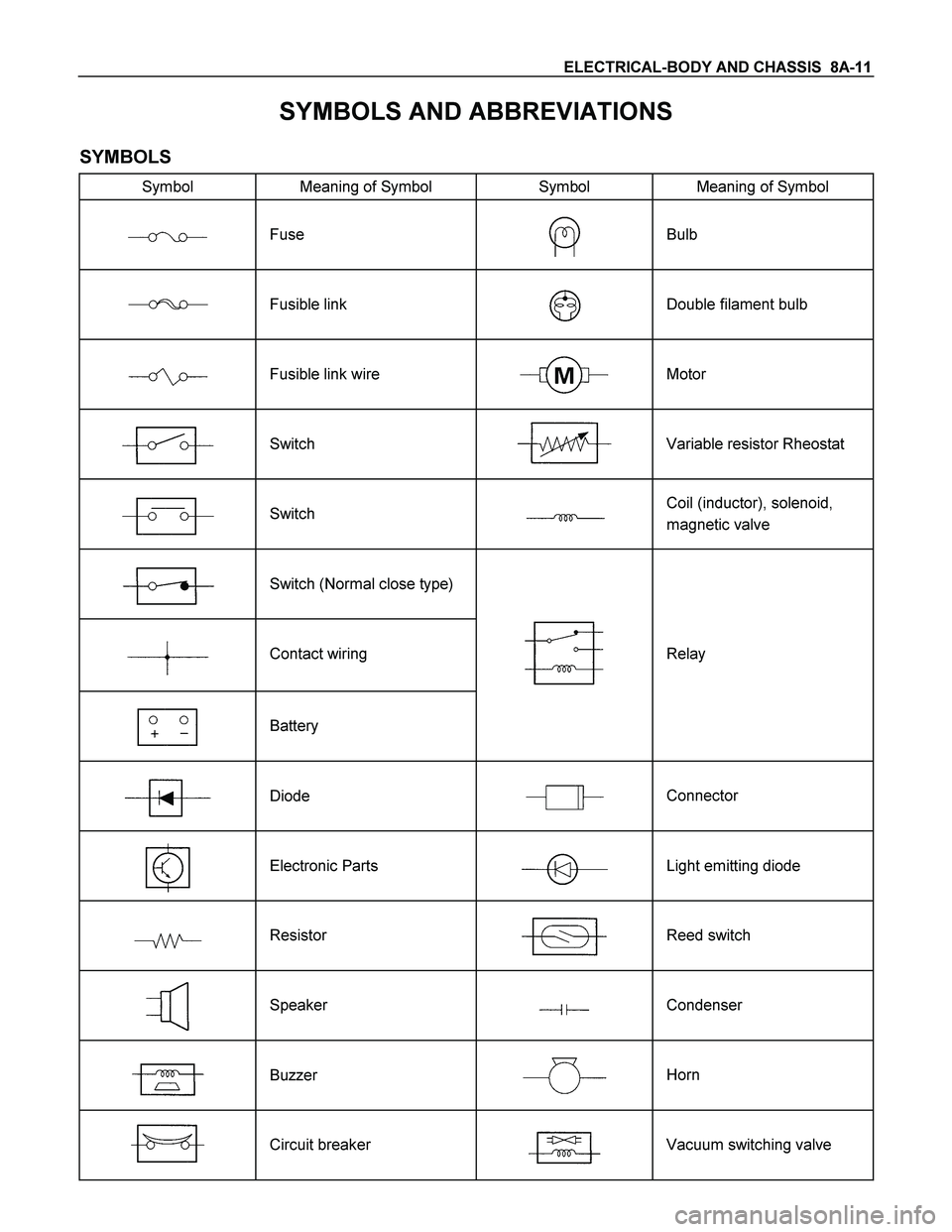
SYMBOLS
Symbol Meaning of Symbol Symbol Meaning of Symbol
Fuse
Bulb
Fusible link
Double filament bulb
Fusible link wire
Motor
Switch
Variable resistor Rheostat
Switch
Coil (inductor), solenoid,
magnetic valve
Switch (Normal close type)
Contact wiring
Relay
Battery
Diode
Connector
Electronic Parts
Light emitting diode
Resistor
Reed switch
Speaker
Condenser
Buzzer
Horn
Circuit breaker
Vacuum switching valve
Page 673 of 4264
ELECTRICAL-BODY AND CHASSIS 8A-15
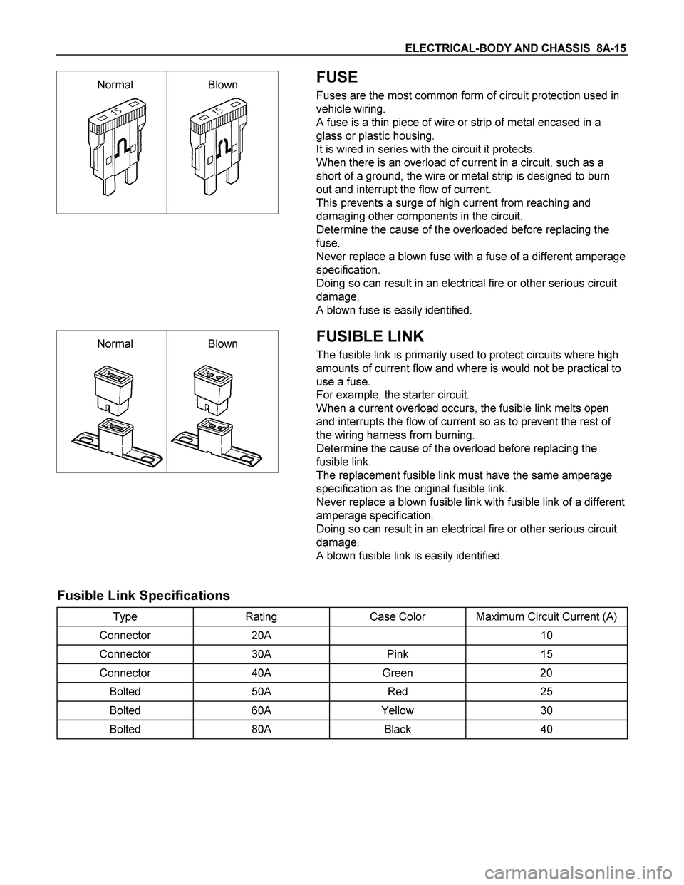
Normal Blown
FUSE
Fuses are the most common form of circuit protection used in
vehicle wiring.
A fuse is a thin piece of wire or strip of metal encased in a
glass or plastic housing.
It is wired in series with the circuit it protects.
When there is an overload of current in a circuit, such as a
short of a ground, the wire or metal strip is designed to burn
out and interrupt the flow of current.
This prevents a surge of high current from reaching and
damaging other components in the circuit.
Determine the cause of the overloaded before replacing the
fuse.
Never replace a blown fuse with a fuse of a different amperage
specification.
Doing so can result in an electrical fire or other serious circuit
damage.
A blown fuse is easily identified.
Normal Blown
FUSIBLE LINK
The fusible link is primarily used to protect circuits where high
amounts of current flow and where is would not be practical to
use a fuse.
For example, the starter circuit.
When a current overload occurs, the fusible link melts open
and interrupts the flow of current so as to prevent the rest of
the wiring harness from burning.
Determine the cause of the overload before replacing the
fusible link.
The replacement fusible link must have the same amperage
specification as the original fusible link.
Never replace a blown fusible link with fusible link of a different
amperage specification.
Doing so can result in an electrical fire or other serious circuit
damage.
A blown fusible link is easily identified.
Fusible Link Specifications
Type Rating Case Color Maximum Circuit Current (A)
Connector 20A 10
Connector 30A Pink 15
Connector 40A Green 20
Bolted 50A Red 25
Bolted 60A Yellow 30
Bolted 80A Black 40
Page 684 of 4264
8A-26 ELECTRICAL-BODY AND CHASSIS
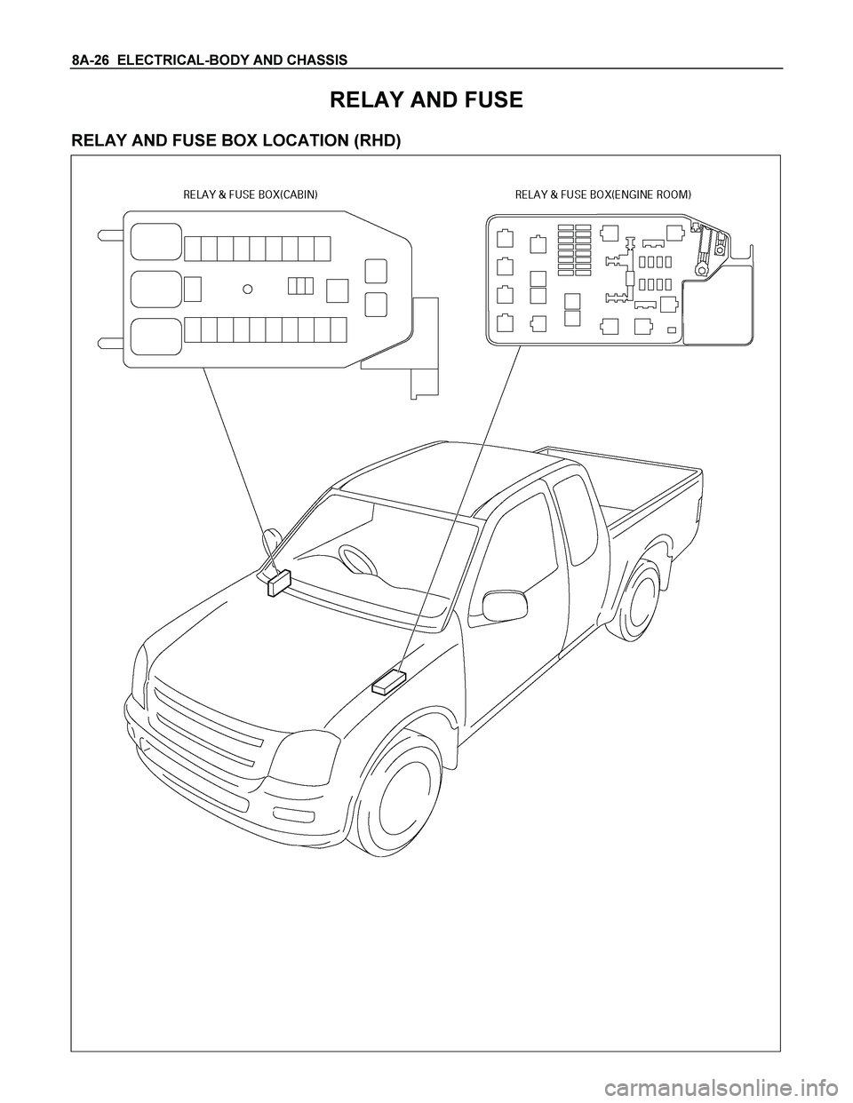
RELAY AND FUSE
RELAY AND FUSE BOX LOCATION (RHD)
Page 685 of 4264
ELECTRICAL-BODY AND CHASSIS 8A-27
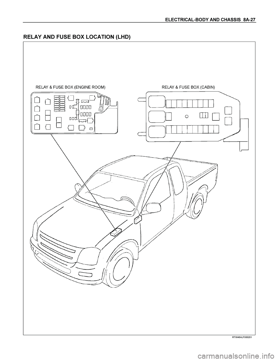
RELAY AND FUSE BOX LOCATION (LHD)
RTW48ALF000201