Page 765 of 4264

ELECTRICAL-BODY AND CHASSIS 8A-107
REMOVAL AND INSTALLATION
ECM (ENGINE CONTROL MODULE):
4JA1-TC / 4JH1-TC
Removal
1. Remove the passenger side front seat – refer to Section 10
CAB.
2. Remove the passenger side front door opening scuff plate.
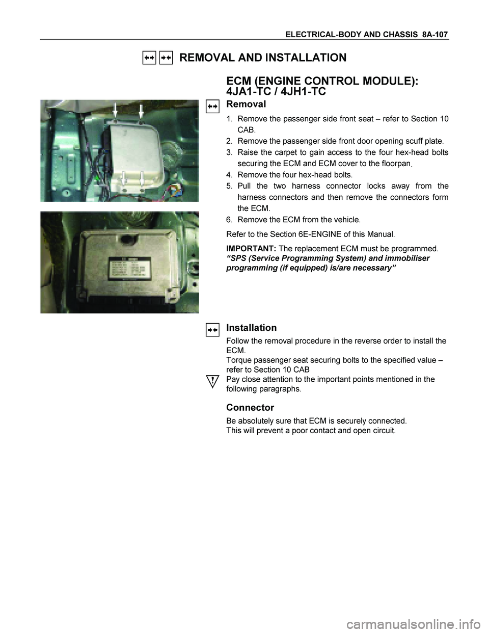
3. Raise the carpet to gain access to the four hex-head bolts
securing the ECM and ECM cover to the floorpan
.
4. Remove the four hex-head bolts.
5. Pull the two harness connector locks away from the
harness connectors and then remove the connectors form
the ECM.
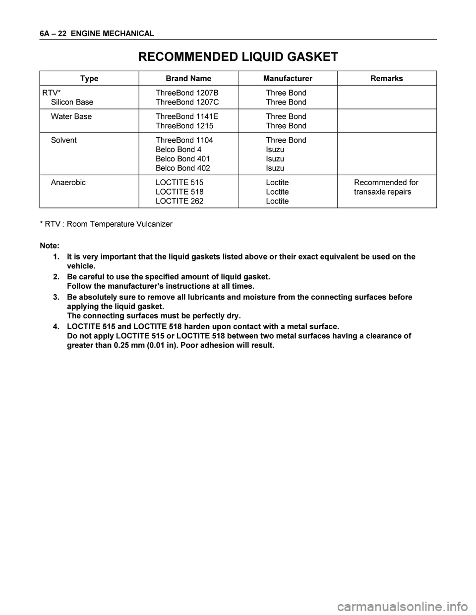
6. Remove the ECM from the vehicle.
Refer to the Section 6E-ENGINE of this Manual.
IMPORTANT: The replacement ECM must be programmed.
“SPS (Service Programming System) and immobiliser
programming (if equipped) is/are necessary”
Installation
Follow the removal procedure in the reverse order to install the
ECM.
Torque passenger seat securing bolts to the specified value –
refer to Section 10 CAB
Pay close attention to the important points mentioned in the
following paragraphs.
Connector
Be absolutely sure that ECM is securely connected.
This will prevent a poor contact and open circuit.
Page 766 of 4264
8A-108 ELECTRICAL-BODY AND CHASSIS
REMOVAL AND INSTALLATION
FUEL PUMP
Removal
1. Remove the fuel tank.
Refer to the Section 6C-ENGINE FUEL of this Manual.
� Disconnect the fuel pipe.
Installation
Follow the removal procedure in the reverse order to install the
fuel pump.
Pay close attention to the important points mentioned in the
following paragraphs.
Rubber Seal
Be absolutely sure that the fuel pump rubber seals correctly
seated.
Connector
Be absolutely sure that the fuel pump connector is securely
connected.
This will prevent a poor contact and an open circuit.
Page 870 of 4264
8A-212 ELECTRICAL-BODY AND CHASSIS
Windshield Washer Spray
Be sure that the engine hood is completely closed before
checking the windshield washer spray adjustment.
Windshield Washer Spray Position: Refer to the illustration.
RTW38DSF000201
Connector
Be absolutely sure that the wiper motor connector is securely
connected.
This will prevent a poor contact and an open circuit.
Note:
Windshield wiper arm and blade assembly configurations
are different for the right-hand and left-hand side of the
vehicle.
Be careful not to confuse the right-hand and left-hand side
assemblies.
This illustration is based on RHD model
WASHER TANK MOTOR
Removal
1. Remove the head light.
� Refer to the head light in this manual.
2. Remove the inner riner.
3. Pull out the clip washer filler.
4. Remove the washer tank nuts.
Page 936 of 4264

8A-278 ELECTRICAL-BODY AND CHASSIS
Low Fuel Indicator Light Inspection
1. Disconnect the fuel tank unit wire connector.
2. Turn the key switch on. Check that the bulb lights.
If operation is not correct, remove and check the bulb or circuit.
or If check whether low fuel turns on fuel input (B-24) at the
time of open and key on.
� meter is check at low fuel
140R300006
Check level sensor operation
1. Remove the fuel tank unit.
2.
Apply battery voltage between terminal (B) and (C) through
a 1.12 watt bulb. Check that the bulb lights.
Note:
It will take a short time for the bulb light.
3. Submerge the sensor in fuel. Check that the bulb goes out.
If operation is not correct, replace the fuel tank unit.
BRAKE SYSTEM WARNING LIGHT
The brake system warning light comes on while the parking
brake is set and the engine run position.
Note:
The parking brake indicator light circuit is designed to
prevent driving of the vehicle with the parking brake on.
It does not indicate the condition of the parking brake
system.
The parking brake switch is in parallel with the brake fluid
switch.
The brake system warning light also comes on when reservoir
brake fluid level falls below the specified limit with the parking
brake released and the engine run position.
Page 1162 of 4264

6A – 22 ENGINE MECHANICAL
RECOMMENDED LIQUID GASKET
Type Brand Name Manufacturer Remarks
RTV*
Silicon Base ThreeBond 1207B
ThreeBond 1207C Three Bond
Three Bond
Water Base ThreeBond 1141E
ThreeBond 1215 Three Bond
Three Bond
Solvent ThreeBond 1104
Belco Bond 4
Belco Bond 401
Belco Bond 402 Three Bond
Isuzu
Isuzu
Isuzu
Anaerobic LOCTITE 515
LOCTITE 518
LOCTITE 262 Loctite
Loctite
Loctite Recommended for
transaxle repairs
* RTV : Room Temperature Vulcanizer
Note:
1. It is very important that the liquid gaskets listed above or their exact equivalent be used on the
vehicle.
2. Be careful to use the specified amount of liquid gasket.
Follow the manufacturer’s instructions at all times.
3. Be absolutely sure to remove all lubricants and moisture from the connecting surfaces before
applying the liquid gasket.
The connecting surfaces must be perfectly dry.
4. LOCTITE 515 and LOCTITE 518 harden upon contact with a metal surface.
Do not apply LOCTITE 515 or LOCTITE 518 between two metal surfaces having a clearance of
greater than 0.25 mm (0.01 in). Poor adhesion will result.
Page 1163 of 4264
ENGINE MECHANICAL 6A – 23
LOCTITE APPLICATION PROCEDURE
LOCTITE Type LOCTITE Color Application Steps
LOCTITE 242 Blue
LOCTITE 262 Red
LOCTITE 270 Green
LOCTITE 271 Red 1. Completely remove all lubricant and moisture from the bolts and the
female threaded surfaces of the parts to be joined.
The surfaces must be perfectly dry.
2. Apply LOCTITE to the bolts.
3. Tighten the bolts to the specified torque.
4. Wait at least one hour before continuing the installation procedure.
LOCTITE 515 Violet 1. Completely remove lubricant and moisture from the connecting
surfaces.
The surfaces must be perfectly dry.
2. Apply a 2.0 – 2.5 mm bead of LOCTITE to one of the connecting
surfaces.
There must be no gaps in the bead.
3. Tighten the bolts to the specified torque.
4. Let the joined parts set for at least thirty minutes.
Page 1165 of 4264

ENGINE MECHANICAL 6A – 25
Replenished Engine Oil MAX lit (US/UK gal)
Condition
Model Engine Dry
With oil filter
replacement Without oil
filter
replacement
4 � 2
4 � 4
(4JA1L/TC)6.2 (1.64/1.36) 5.2 � 4.2
(1.37 � 1.11
/ 1.14 � 0.92) 4.5 � 3.5
(1.19 � 0.93
/ 0.99 � 0.77)
4 � 2
(4JH1TC)
6.2 (1.64/1.36) 5.2 � 4.2
(1.37 � 1.11
/ 1.14 � 0.92) 4.5 � 3.5
(1.19 � 0.93
/ 0.99 � 0.77)
4 � 4
(4JH1TC) 7.0 (1.85/1.54) 6.2 � 5.2
(1.64 � 1.37
/ 1.36 � 1.14) 5.3 � 4.3
(1.72 � 1.14
/ 1.17 � 0.95)
9. Start the engine and check for oil leakage from the
main oil filter.
6A-7
FUEL SYSTEM
Fuel Filter Replacement Procedure
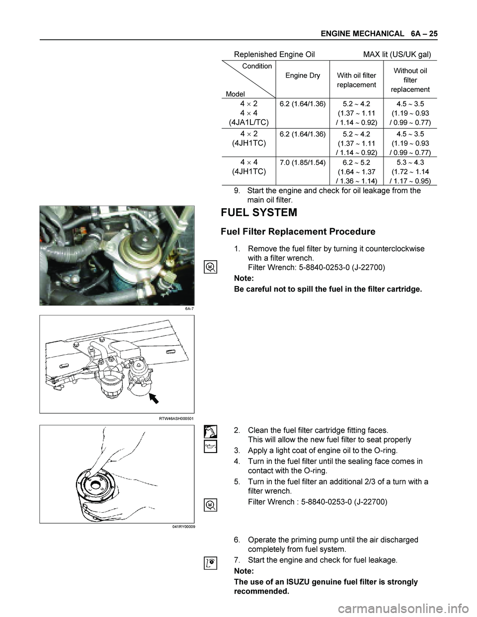
1. Remove the fuel filter by turning it counterclockwise
with a filter wrench.
Filter Wrench: 5-8840-0253-0 (J-22700)
Note:
Be careful not to spill the fuel in the filter cartridge.
RTW46ASH000501
2. Clean the fuel filter cartridge fitting faces.
This will allow the new fuel filter to seat properly
3. Apply a light coat of engine oil to the O-ring.
4. Turn in the fuel filter until the sealing face comes in
contact with the O-ring.
5. Turn in the fuel filter an additional 2/3 of a turn with a
filter wrench.
Filter Wrench : 5-8840-0253-0 (J-22700)
6. Operate the priming pump until the air discharged
completely from fuel system.
7. Start the engine and check for fuel leakage.
Note:
The use of an ISUZU genuine fuel filter is strongly
recommended.
041RY00009
Page 1167 of 4264

ENGINE MECHANICAL 6A – 27
111R300001
COOLING SYSTEM
Coolant Level
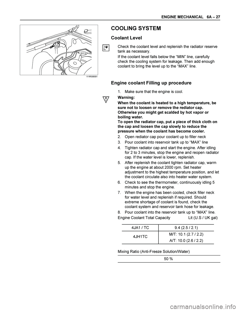
Check the coolant level and replenish the radiator reserve
tank as necessary.
If the coolant level falls below the “MIN” line, carefully
check the cooling system for leakage. Then add enough
coolant to bring the level up to the “MAX” line.
Engine coolant Filling up procedure
1. Make sure that the engine is cool.
Warning:
When the coolant is heated to a high temperature, be
sure not to loosen or remove the rediator cap.
Otherwise you might get scalded by hot vapor or
boiling water.
To open the radiator cap, put a piece of thick cloth on
the cap and loosen the cap slowly to reduce the
pressure when the coolant has become cooler.
2. Open rediator cap pour coolant up to filler neck
3. Pour coolant into reservoir tank up to “MAX” line
4. Tighten radiator cap and start the engine. After idling
for 2 to 3 minutes, stop the engine and reopen radiator
cap. If the water level is lower, replenish.
5. After replenish the coolant tighten radiator cap, warm
up the engine at about 2000 rpm. Set heater
adjustment to the highest temperature position, and let
the coolant circulate also into heater water system.
6. Check to see the thermometer, continuously idling 5
minutes and stop the engine.
7. When the engine has been cooled, check filler neck
for water level and replenish if required. Should
extreme shortage of coolant is found, check the
coolant system and reservoir tank hose for leakage.
8. Pour coolant into the reservoir tank up to “MAX” line.
Engine Coolant Total Capacity Lit (U.S / UK gal)
4JA1 / TC 9.4 (2.5 / 2.1)
4JH1TC M/T: 10.1 (2.7 / 2.2)
A/T: 10.0 (2.6 / 2.2)
Mixing Ratio (Anti-Freeze Solution/Water)
50 %