Page 4173 of 4264
 7A3-21
4. Remove the shift cable from the transmission.
P1010068
5. Remove the rear propeller shaft assembly.
6. Loosen (do not remove) the nuts securing the
exhaust")
ON-VEHICLE SERVICE (JR405E) 7A3-21
4. Remove the shift cable from the transmission.
P1010068
5. Remove the rear propeller shaft assembly.
6. Loosen (do not remove) the nuts securing the
exhaust manifold and the exhaust pipe.
7. Disconnect the harness connectors from the
transmission.
8. Remove the fuel pipe bracket.
P1010013
P1010014
9. Remove the ATF level dipstick and tube.
10. Remove the undercover.
11. Rotate the ring gear and remove the 6 torque
converter bolts.
P1010016
12. Remove the automatic transmission fluid cooling
pipe.
P1010060
13. Place a jack beneath the engine to support it.
14. Remove the 3rd crossmember.
15. Remove the transmission mount.
16. Lower the jack beneath the engine slightly to tilt the
engine and transmission. Do not allow the radiato
r
and air conditioner hoses to stretch.
17. Remove the bolts attaching the transmission to the
engine.
18. Lower the transmission from beneath the vehicle.
Take care not to damage the breathers.
Install or Connect
1. Install the transmission to the engine and tighten the
bolts.
Bolt torque : M10 40 N·m (30 lb·ft)
M12 76 N·m (56 lb·ft)
2. Install the cable bracket to the transmission.
3. Connect the engine harness connectors.
Page 4174 of 4264
7A3-22 ON-VEHICLE SERVICE (JR405E)
4. Install the 3rd crossmember.
Bolt and Nut torque : 67 N·m (49 lb·ft)
Bolt torque : 50 N·m (37 lb·ft)
5. Install the automatic transmission fluid cooling pipe.
6. Install the torque converter bolts.
Bolt torque : 29 N·m (22 lb·ft)
7. Install the undercover.
Bolt torque : 9 N·m (78 lb·in)
8. Install the ATF level dipstick and tube.
9. Install the fuel hose bracket.
Bolt torque : 6 N·m (52 lb·in)
10. Tighten the nuts securing the exhaust manifold and
the exhaust pipe.
Bolt torque : 43 N·m (32 lb·ft)
11. Install the rear propeller shaft assembly.
Flange bolt torque : 63 N·m (46 lb·ft)
Center bearing bracket bolt torque :
69 N·m (51 lb·ft)
12. Install the shift cable.
13. Connect the negative battery cable.
14. Remove the safety stands.
15. Remove the wheels blocks.
Torque Specifications
RTW37ALF001501
Page 4177 of 4264
UNIT REPAIR (JR405E) 7A4-3
Disassembly steps
1. Torque converter
� Pull the torque converter free.
NOTE:
Place a pan beneath the torque converter to catch
automatic transmission fluid (ATF) spillage.
� Draining the ATF from the torque converter.
01ASSY101
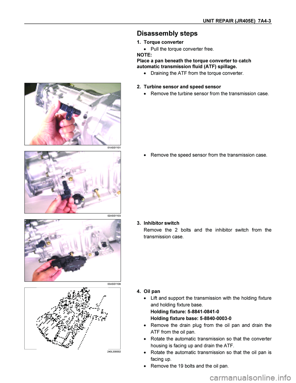
2. Turbine sensor and speed sensor
� Remove the turbine sensor from the transmission case.
02ASSY103
�
Remove the speed sensor from the transmission case.
03ASSY106
3. Inhibitor switch
Remove the 2 bolts and the inhibitor switch from the
transmission case.
240L300002
4. Oil pan
� Lift and support the transmission with the holding fixture
and holding fixture base.
Holding fixture: 5-8841-0841-0
Holding fixture base: 5-8840-0003-0
� Remove the drain plug from the oil pan and drain the
ATF from the oil pan.
� Rotate the automatic transmission so that the converte
r
housing is facing up and drain the ATF.
� Rotate the automatic transmission so that the oil pan is
facing up.
� Remove the 19 bolts and the oil pan.
Page 4233 of 4264
UNIT REPAIR (JR405E) 7A4-59
18CASE-AY43
�
Use a pin punch to drive the manual plate spring pin into
place.
21CASE-AY48
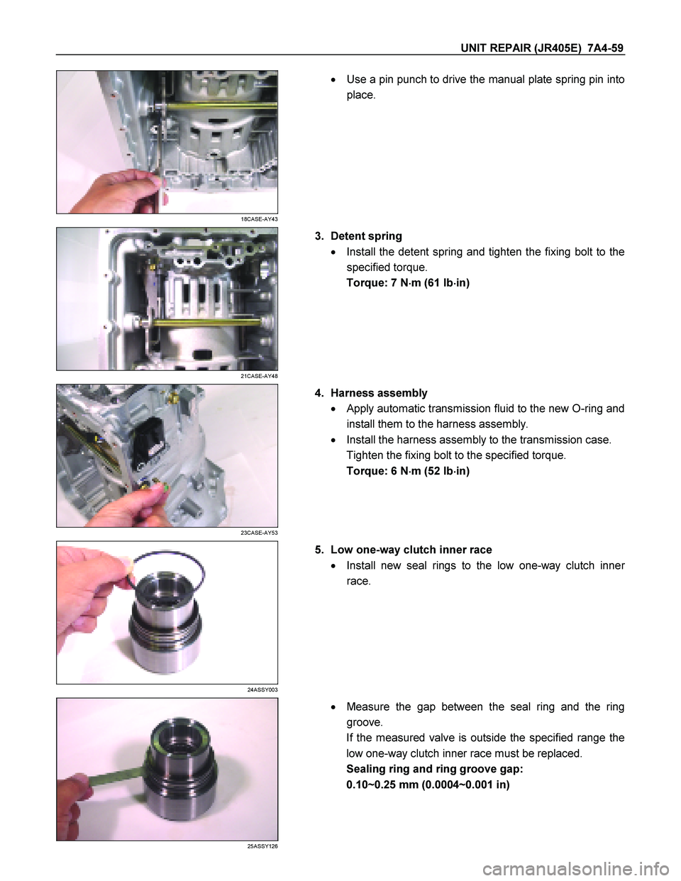
3. Detent spring
� Install the detent spring and tighten the fixing bolt to the
specified torque.
Torque: 7 N �
��
�
m (61 Ib �
��
�
in)
23CASE-AY53
4. Harness assembly
� Apply automatic transmission fluid to the new O-ring and
install them to the harness assembly.
� Install the harness assembly to the transmission case.
Tighten the fixing bolt to the specified torque.
Torque: 6 N �
��
�
m (52 Ib �
��
�
in)
24ASSY003
5. Low one-way clutch inner race
� Install new seal rings to the low one-way clutch inne
r
race.
25ASSY126
�
Measure the gap between the seal ring and the ring
groove.
If the measured valve is outside the specified range the
low one-way clutch inner race must be replaced.
Sealing ring and ring groove gap:
0.10~0.25 mm (0.0004~0.001 in)
Page 4244 of 4264

AUTOMATIC TRANSMISSION
REASSEMBLY
Assembly cautions
� Use your bare hands or vinyl gloves to reassemble the
transmission. Do not use ordinary work gloves (loosen")
7A4-70 UNIT REPAIR (JR405E)
AUTOMATIC TRANSMISSION
REASSEMBLY
Assembly cautions
� Use your bare hands or vinyl gloves to reassemble the
transmission. Do not use ordinary work gloves (loosen
threads from the gloves may fall into the transmission
and cause problems).
� Before installing the drive plates, immerse them in the
recommended automatic transmission fluid (BESCO
ATF II or ATF III). If the drive plate is new, it must be
immersed for at least two hours to ensure oil penetration
and saturation of the facing.
�
Apply ATF to all sliding and contact surfaces before
assembly. Also apply ATF to seal rings and O-rings.
Assemble the parts carefully to avoid damaging them.
� Replace any snap ring that appears worn, bent out o
f
shape, or otherwise damaged.
� If any part contacting the transmission case is damaged,
it must be replaced with a new part.
� Be careful not to damage the plates during reassembly
(oil leakage from the plate will result).
� If you are reusing a seal, remove the old adhesive agen
t
and clean the surface with cleaning oil before applying
the new adhesive agent.
� Wait at least two hours after installing the oil seals
before installing the plates.
� Do not replace O-rings, snap rings, bearings, and/o
r
bearing races with inferior substitutes.
Page:
< prev 1-8 9-16 17-24

4. Install the 3rd crossmember.
Bolt and Nut torque : 67 N·m (49 lb·ft)
Bolt torque : 50 N·m (37 lb·ft)
5. Install the automatic transmission fluid")