Page 1320 of 4264

6C – 20 FUEL SYSTEM
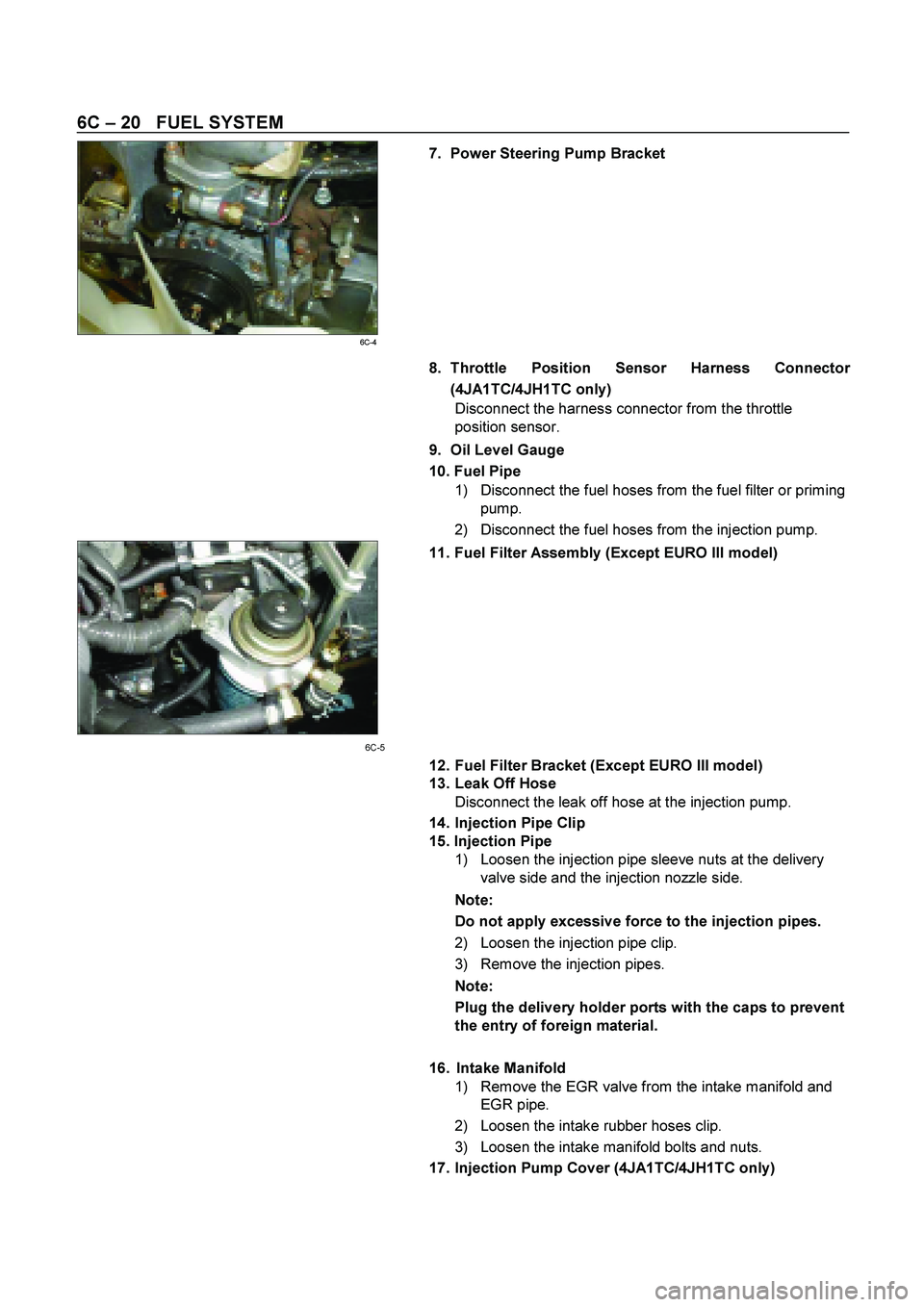
7. Power Steering Pump Bracket
6C-4 8. Throttle Position Sensor Harness Connector
(4JA1TC/4JH1TC only)
Disconnect the harness connector from the throttle
position sensor.
9. Oil Level Gauge
10. Fuel Pipe
1) Disconnect the fuel hoses from the fuel filter or priming
pump.
2) Disconnect the fuel hoses from the injection pump.
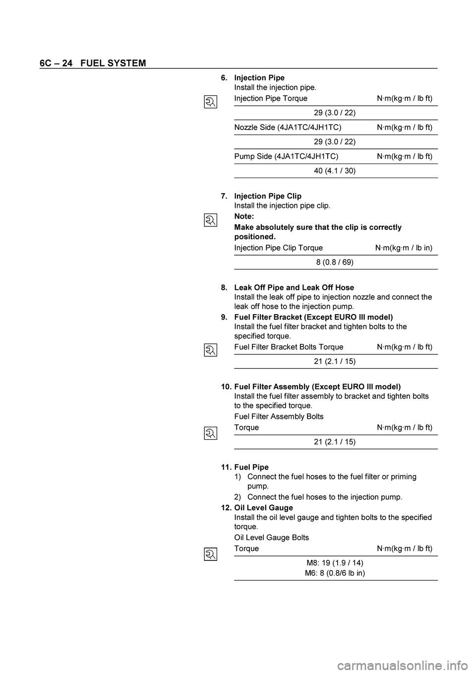
11. Fuel Filter Assembly (Except EURO III model)
6C-5
12. Fuel Filter Bracket (Except EURO III model)
13. Leak Off Hose
Disconnect the leak off hose at the injection pump.
14. Injection Pipe Clip
15. Injection Pipe
1) Loosen the injection pipe sleeve nuts at the delivery
valve side and the injection nozzle side.
Note:
Do not apply excessive force to the injection pipes.
2) Loosen the injection pipe clip.
3) Remove the injection pipes.
Note:
Plug the delivery holder ports with the caps to prevent
the entry of foreign material.
16. Intake Manifold
1) Remove the EGR valve from the intake manifold and
EGR pipe.
2) Loosen the intake rubber hoses clip.
3) Loosen the intake manifold bolts and nuts.
17. Injection Pump Cover (4JA1TC/4JH1TC only)
Page 1324 of 4264

6C – 24 FUEL SYSTEM
6. Injection Pipe
Install the injection pipe.
Injection Pipe Torque N·m(kg·m / lb ft)
29 (3.0 / 22)
Nozzle Side (4JA1TC/4JH1TC) N·m(kg·m / lb ft)
29 (3.0 / 22)
Pump Side (4JA1TC/4JH1TC) N·m(kg·m / lb ft)
40 (4.1 / 30)
7. Injection Pipe Clip
Install the injection pipe clip.
Note:
Make absolutely sure that the clip is correctly
positioned.
Injection Pipe Clip Torque N·m(kg·m / lb in)
8 (0.8 / 69)
8. Leak Off Pipe and Leak Off Hose
Install the leak off pipe to injection nozzle and connect the
leak off hose to the injection pump.
9. Fuel Filter Bracket (Except EURO III model)
Install the fuel filter bracket and tighten bolts to the
specified torque.
Fuel Filter Bracket Bolts Torque N·m(kg·m / lb ft)
21 (2.1 / 15)
10. Fuel Filter Assembly (Except EURO III model)
Install the fuel filter assembly to bracket and tighten bolts
to the specified torque.
Fuel Filter Assembly Bolts
Torque N·m(kg·m / lb ft)
21 (2.1 / 15)
11. Fuel Pipe
1) Connect the fuel hoses to the fuel filter or priming
pump.
2) Connect the fuel hoses to the injection pump.
12. Oil Level Gauge
Install the oil level gauge and tighten bolts to the specified
torque.
Oil Level Gauge Bolts
Torque N·m(kg·m / lb ft)
M8: 19 (1.9 / 14)
M6: 8 (0.8/6 lb in)
Page 1327 of 4264
FUEL SYSTEM 6C – 27
REASSEMBLY
080L200010
Reassembly Steps
1.
Nozzle holder body 9.
Spring seat
2.
Shim (First opening pressure
adjustment) 10.
Lift Piece
3.
First spring 11.
Spacer & pin
4.
Spring seat 12.
Nozzle & pin
5.
Collar 13.
Retaining nut
6.
Second spring 14.
Gasket
7.
Push rod 15.
Eye bolt
8.
Shim (Second opening pressure
adjustment)
Important Operations
The nozzle holder is adjusted as the components are
reassembled in the sequence above.
As adjustment of the two-spring nozzle holder is made in
hundredths of a millimeter, clean the parts thoroughly in
light oil to completely remove any dirt or foreign matter.
Page 1337 of 4264
FUEL SYSTEM 6C – 37
4. Set the nozzle holder to the nozzle tester and check
first nozzle opening pressure, spray condition, seat oil
tightness and each part for oil leaks.
5. When replacing the nozzle, replace the nozzle, lift
piece, pins and spacer as a set with the nozzle service
kit.
CAUTION:
Pre-lift will not be as specified if only the nozzle is
replaced.
040MV030.tif
Page 1348 of 4264
6D – 10 ENGINE ELECTRICAL
RTW46DSH000101
Important Operations
1. Vacuum Pump
1. Loosen the vacuum pump fixing screws.
2. Support the vacuum pump O-ring.
3. Carefully remove the O-ring.
2. Cover
RTW46DSH000201
3. Through Bolt
1. Remove the M5 through bolt.
2. Separate the front and rear sides of the vacuum pump.
3. Insert the tips of 2 ordinary screwdrivers into the space
between the front cover and the stator core. Remove
the front cover and rotor together with the rear cover
and stator.
If removal is difficult, push the rear cover to the side and
lightly tap the end of the shaft with a plastic hammer to
loosen it.
� The front cover oil seal must be replaced with a new
one when the front cover is removed.
� Take care not to damage the stator core with the
screwdriver tips.
RTW46DSH000601
RTW46DSH002101
4. Pulley
1. Carefully clamp the rotor assembly in a vise.
2. Loosen the pulley nut.
3. Remove the pulley and the front cover from the rotor.
Page 1349 of 4264
ENGINE ELECTRICAL 6D – 11
RTW46DSH000301
7. Rotor Assembly
1. Remove the rotor from front cover assembly.
Remove the front cover stator and rectifier.
RTW46DSH000701
8. Front Cover Assembly
1. Remove the front cover bearing retainer screws.
2. Remove the bearing.
RTW46DSH000801
9. Rear rotor bearing
� Re-use improper parts.
10. Rectifier
1. Disconnect the stator coil leads between each rectifier
by melting the solder connection.
Hold the lead wire between the solder and the rectifier
with a pair of long nose pliers.
This will prevent heat transfer and resultant damage to
the rectifier.
RTW46DSH000401
Page 1350 of 4264
6D – 12 ENGINE ELECTRICAL
INSPECTION AND REPAIR
Make the necessary adjustments, repairs, and part replacement if excessive wear or damage is discovered during
inspection.
ROTOR ASSEMBLY
1. Inspect the slip ring faces for dirt and pitting. Wipe away any dirt with a clean cloth soaked in
alcohol.
2. Measure the slip ring diameter.
Slip Ring Diameter mm (in)
Standard Limit
RTW06DSH000101
31.6 (1.245) 30.6 (1.183)
If the slip ring diameter is less than the specified limit, the
slip rings must be replaced.
3. Measure the rotor coil resistance.
Rotor Coil Resistance at 20 �C (68 �F) ohms
Standard 3.8
RTW46DSH001001
RTW46DSH001101
4. Check for continuity between the slip rings and the
rotor core or shaft.
If there is continuity, the entire rotor assmbly must be
replaced.
Page 1351 of 4264
ENGINE ELECTRICAL 6D – 13
STATOR COIL ASSEMBLY
1. Check for continuity across the stator coils.
If there is no continuity, the stator coils must be
replaced.
Resistance Between The Terminal “N” and the Coil Ends
(Reference) ohms
Standard 0.1
066RY00022 2. Check for continuity between each stator coils and the
stator core.
If there is continuity, the stator coils must be replaced.
066RY00023
RTW46DSH004801
BRUSH
Measure the length of the brush. If abrasion has reduced
the brush length to less than 6.5 mm, the brush must be
replaced with a new one.
A wear line is inscribed in the brush. If the line is not
visible, the brush must be replaced.
Brush Length (Reference) mm (in)
Standard Limit
25 (1.0) 6.5 (0.25)
RTW46DSH001201
Rectifier
Tester wire
E BAT
U, V, and WN ⊕ � U, V, and WN⊕ �
⊕ ----- Conductivity ⊕ ----- No
conductivity
�
No
conductivity -----
� Conductivity -----
Negative side diode check Positive side diode check