Page 1283 of 4264

Delivery volume lit (US/UK gal)/min")
ENGINE COOLING 6B – 3
MAIN DATA AND SPECIFICATIONS
Description Item
M/T A/T
Cooling system
Water pump type
Pump to crankshaft speed ratio (To 1)
Delivery volume lit (US/UK gal)/min
Pump speed at 3000 rpm
Water temperature at 30�C (86�F)
Pump bearing type
Thermostat type
Valve initial opening temperature �C (�F)
(Oil cooler thermo valve)
(EGR cooler thermo valve)
Valve full opening temperature �C (�F)
(Oil cooler thermo valve)
(EGR cooler thermo valve)
Valve lift at fully open position mm (in)
(Oil cooler thermo valve)
(EGR cooler thermo valve) Engine coolant forced circulation
Centrifugal impeller type
1.2
100 (26.3/22.2)
Double row shaft
Wax pellet with jiggle valve
82 (180)
76.5 (170)
40 (104)
95 (203)
90 (194)
55 (131)
9.5 (0.37)
4.5 (0.18)
3.5 (0.14)
Radiator Tube type corrugated
Heat radiation capacity 93.0 kw (79,980 kcal/h)
Heat radiation area
11.63 m� (1.081ft�)
Radiator front area
0.28m� (0.026 ft�)
Radiator dry weight 52 N (5.3 kg/11.7 lb) 53 N (5.4 kg/11.9 lb)
Radiator cap valve opening pressure
93.3 � 122.7kpa (13.5 � 17.8psi)
Engine coolant capacity 2.4 lit (5.1 U.S pint) 2.3 lit (4.9 U.S pint)
Engine coolant total capacity 10.1 lit (21.3 U.S pint) 10.0 lit (21.1 U.S pint)
Page 1286 of 4264
6B – 6 ENGINE COOLING
110RS001
RADIATOR
The radiator is a tube type with corrugated fins. In order to
raise the boiling point of the coolant, the radiator is fitted with a
cap in which the valve is operated at 93.3
� 122.7 kPa (13.5 �
17.8 psi) pressure. (No oil cooler provided for M/T)
F06RW005
Antifreeze Solution
NOTE: Antifreeze solution + Water = Total cooling system
capacity.
Total Cooling System Capacity Lit (US / UK gal)
9.4 (2.5/21) 4JA1L/TC
M/T 10.1 (2.7/2.2) 4JH1TC
A/T 10.0 (2.6/2.2) 4JH1TC
See section 0B MAINTENACE AND LUBRICATION.
PTW46BSH000201
NOITE:
To maintain the corrosion resistance of the aluminum
radiator, water and antifreeze must be combined in a 1:1
solution (50% antifreeze and 50% water)
NOTE
Page 1287 of 4264
ENGINE COOLING 6B – 7
DIAGNOSIS
Engine Cooling Trouble
Symptom Possible Cause Action
Low Engine Coolant level Replenish
Thermo meter unit faulty Replace
Faulty thermostat Replace
Faulty Engine Coolant temperature
sensor Repair or replace
Clogged radiator Clean or replace
Faulty radiator cap Replace
Low engine oil level or use of
improper engine oil Replenish or change oil
Clogged exhaust system Clean exhaust system or replace
faulty parts
Faulty Throttle Position sensor Replace throttle valve assembly
Open or shorted Throttle Position
sensor circuit Repair or replace
Engine overheating
Damaged cylinder head gasket Replace
Engine overcooling Faulty thermostat Replace
Faulty thermostat Replace Engine slow to warm–up
Thermo unit faulty Replace
Page 1288 of 4264

6B – 8 ENGINE COOLING
Draining and Refilling Cooling System
Before draining the cooling system, inspect the system and
perform any necessary service to ensure that it is clean, does
not leak and is in proper working order. The engine coolan
t
(EC) level should be between the “MIN" and “MAX" lines o
f
reserve tank when the engine is cold. If low, check for leakage
and add EC up to the “MAX" line.
There should not be any excessive deposit of rust or scales
around the radiator cap or radiator filler hole, and the EC
should also be free from oil.
Replace the EC if excessively dirty.
P1010064
1. Completely drain the cooling system by opening the drain
plug at the bottom of the radiator.
2. Remove the radiator cap.
WARNING: To avoid the danger of being burned, do not
remove the cap while the engine and radiator are still hot.
Scalding fluid and steam can be blown out unde
r
pressure.
3. Disconnect all hoses from the EC reserve tank.
Scrub and clean the inside of the reserve tank with soap and water. Flush it well with clean water, then drain it.
Install the reserve tank and hoses.
4. Refill the cooling system with the EC using a solution that is at least 50 percent antifreeze.
Procedure for filling with coolant (in case of full change)
� Make sure that the engine is cool.
� Open radiator cap pour coolant up to filler neck.
� Pour coolant into reservoir tank up to “MAX" line.
� Tighten radiator cap and start the engine. After idling for 2
to 3 minutes, stop the engine and reopen radiator cap. If the
water level is lower, replenish.
WARNING: When the coolant is heated to a high
temperature, be sure not to loosen or remove the radiato
r
cap. Otherwise you might get scalded by not vapor or
boiling water. To open the radiator cap, put a piece of
thick cloth on the cap and loosen the cap slowly to reduce
the pressure when the coolant has become cooler.
Page 1296 of 4264
6B – 16 ENGINE COOLING
P1010064
Removal
1. Disconnect battery ground cable.
2. Loosen a drain plug to drain EC.
3. Disconnect oil cooler hose on automatic transmission (A/T).
4. Disconnect radiator inlet hose and outlet hose from the engine.
PTW46BSH000101
5. Remove fan guide(1), clips(2) on both sides and the bottom
lock, then remove lower fan guide(3) with fan shroud(4).
6. Disconnect the reserve tank hose(6) from radiator.
RTW36BMH000101
7. Remove bracket(5).
8. Lift up and remove the radiator assembly with hose, taking
care not to damage the radiator core with a fan blade.
Page 1298 of 4264
6B – 18 ENGINE COOLING
110RS005
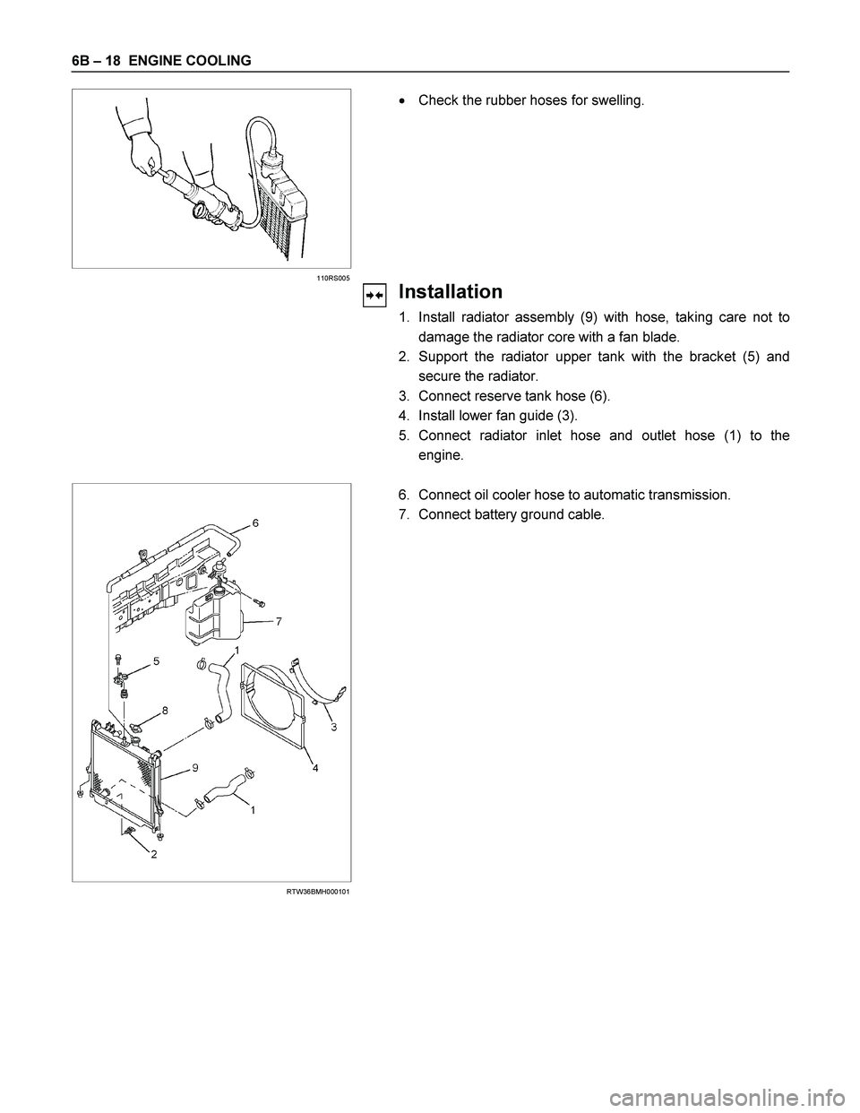
� Check the rubber hoses for swelling.
Installation
1. Install radiator assembly (9) with hose, taking care not to
damage the radiator core with a fan blade.
2. Support the radiator upper tank with the bracket (5) and
secure the radiator.
3. Connect reserve tank hose (6).
4. Install lower fan guide (3).
5. Connect radiator inlet hose and outlet hose (1) to the
engine.
RTW36BMH000101
6. Connect oil cooler hose to automatic transmission.
7. Connect battery ground cable.
Page 1303 of 4264
 4JA1TC 4JH1TC
Injection pump type
Bosch distributor
VE type Bosch distributor VP44 type
Governor type Mech")
FUEL SYSTEM 6C – 3
MAIN DATA AND SPECIFICATIONS
Description Item
4JA1T (L) 4JA1TC 4JH1TC
Injection pump type
Bosch distributor
VE type Bosch distributor VP44 type
Governor type Mechanical variable
(Half speed oil
pressure) Electrical controled
Timer type Oil pressure Electrical controled
Fuel feed pump type Vane with input shaft
Injection nozzle type Hole type
Number of injection nozzle orifices 5
Injection nozzle orifices
Inside diameter mm (in) 0.19 (0.0075) 0.17 (0.0067) 0.21 (0.0083)
19.1 (195) 19.0 (194) 19.5 (199) Injection nozzle designed operating
pressure MPa (kg/cm2) 1st
2nd 25.0 (255) 33.5 (328) 33.8 (331)
Main fuel filter type Disposable cartridge paper element
Precautions
When working on the fuel system, there are several things
to keep in mind:
Any time the fuel system is being worked on,
disconnect the negative battery cable except fo
r
those tests where battery voltage is required.
Always keep a dry chemical (Class B) fire
extinguisher near the work area.
Replace all pipes with the same pipe and fittings that
were removed.
Clean and inspect “O" rings. Replace if required.
Always relieve the line pressure before servicing any
fuel system components.
Do not attempt repairs on the fuel system until you
have read the instructions and checked the pictures
relating to that repair.
Adhere to all Notices and Cautions.
NOTE:
Injection nozzle adjustment is possible only on the 4JA1L
engine.
Page 1316 of 4264

6C – 16 FUEL SYSTEM
140R100037
2. For removal of the quick connector, hold the quick
connector in one hand, and pull out the connector with the
other hand while pressing the square relieve button of the
connector, as illustrated.
NOTE: Do not use tools of any kind. Only use bare hands
when disconnecting the connector. Use a lubricant (light oil)
and/or push and pull the connector until the pipe is
disconnected.
140R100028
Cover the connectors that was removed with a plastic bag,
to prevent dust or rain water from entering.
140R100036
Reuse of Quick–Connector
�
Replace the port and connector if scratch, dent or crack is
found.
� Remove any dirt build up on the port when installing the
connector. Replace the connector, if there is any forms o
f
rust, dent, scratch.
�
After cleaning the port, insert it straight into the connector
until it clicks. After it clicks, try pulling at 49N (5kgf) it out to
make sure that it is not drawn and is securely locked.
Assembling Advice
By applying engine oil or light oil to the pipe, port makes pipe
assembly easier. The pipe assembly should take place
immediately after applying oil (to prevent dust from sticking to
the pipe surface – which may decrease sealing ability).
Test/Inspection After Assembling
1. Reconnect the battery negative cable.
2. Start the engine and observe the engine idle speed. The
presence of dirt in the fuel system may affect the fuel
injection system.
3. Check for fuel leakage from the connector.


.
4. Discon")