Page 3561 of 4264
REAR SUSPENSION 3D-5
LEAF SPRING AND SHOCK ABSORBER
LEAF SPRING AND ASSOCIATED PARTS
460R300001
Legend
1. Parking Brake Cable Bracket
2. Nut and Washer
3. Nut and Washer
4. Shock Absorber
5. Nut
6. U Bolt and Seat
7. Lower Clamp
8. Nut
9. Shackle Plate
10. Shackle Pin
11. Rubber Bushing
12. Nut and Plain Washer
13. Spring Pin
14. Leaf Spring
15. Bump Rubber
Page 3562 of 4264

3D-6 REAR SUSPENSION
F03L100003
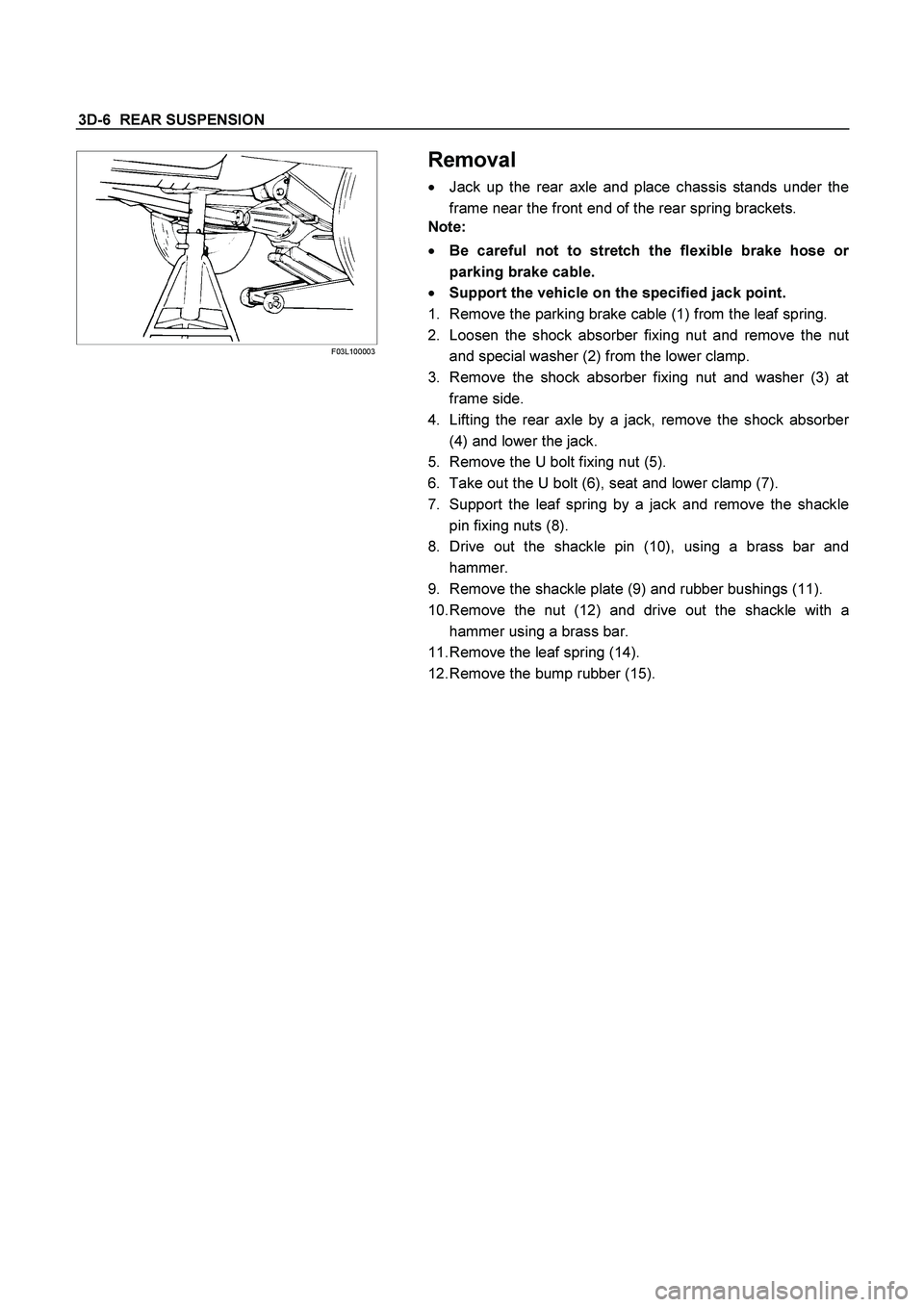
Removal
� Jack up the rear axle and place chassis stands under the
frame near the front end of the rear spring brackets.
Note:
� Be careful not to stretch the flexible brake hose o
r
parking brake cable.
� Support the vehicle on the specified jack point.
1. Remove the parking brake cable (1) from the leaf spring.
2. Loosen the shock absorber fixing nut and remove the nu
t
and special washer (2) from the lower clamp.
3. Remove the shock absorber fixing nut and washer (3) at
frame side.
4. Lifting the rear axle by a jack, remove the shock absorbe
r
(4) and lower the jack.
5. Remove the U bolt fixing nut (5).
6. Take out the U bolt (6), seat and lower clamp (7).
7. Support the leaf spring by a jack and remove the shackle
pin fixing nuts (8).
8. Drive out the shackle pin (10), using a brass bar and
hammer.
9. Remove the shackle plate (9) and rubber bushings (11).
10. Remove the nut (12) and drive out the shackle with a
hammer using a brass bar.
11. Remove the leaf spring (14).
12. Remove the bump rubber (15).
Page 3563 of 4264
REAR SUSPENSION 3D-7
INSPECTION AND REPAIR
Make correction or parts replacement if wear, damage or their abnormal conditions are found through inspection.
Visual Check
Inspect the following parts for wear, damage, nuts or other
abnormal conditions.
� Leaf spring assembly
� Clip
� Center bolt
� U-bolt
� Spring pin
� Shackle pin
� Shock absorber
� Rubber bumper
� Rubber bushing
� Bump rubber seat
Shackle Pin
Shackle Pin diameter mm (in)
17.93 - 18.00 (0.706 - 0.709)
Spring Pin
Spring Pin Diameter mm (in)
13.8 - 14.0 (0.543 - 0.551)
Shock Absorber
Inspection operation of shock absorber
If no resistance is felt while expanding the shock absorber, that
indicates the absorber is faulty.
Page 3564 of 4264

3D-8 REAR SUSPENSION
Installation
1. Install the bump rubber (15) and bolt and tighten it to the
specified torque.
Torque N�m (kg�m/lb�ft)
42 (4.3/31)
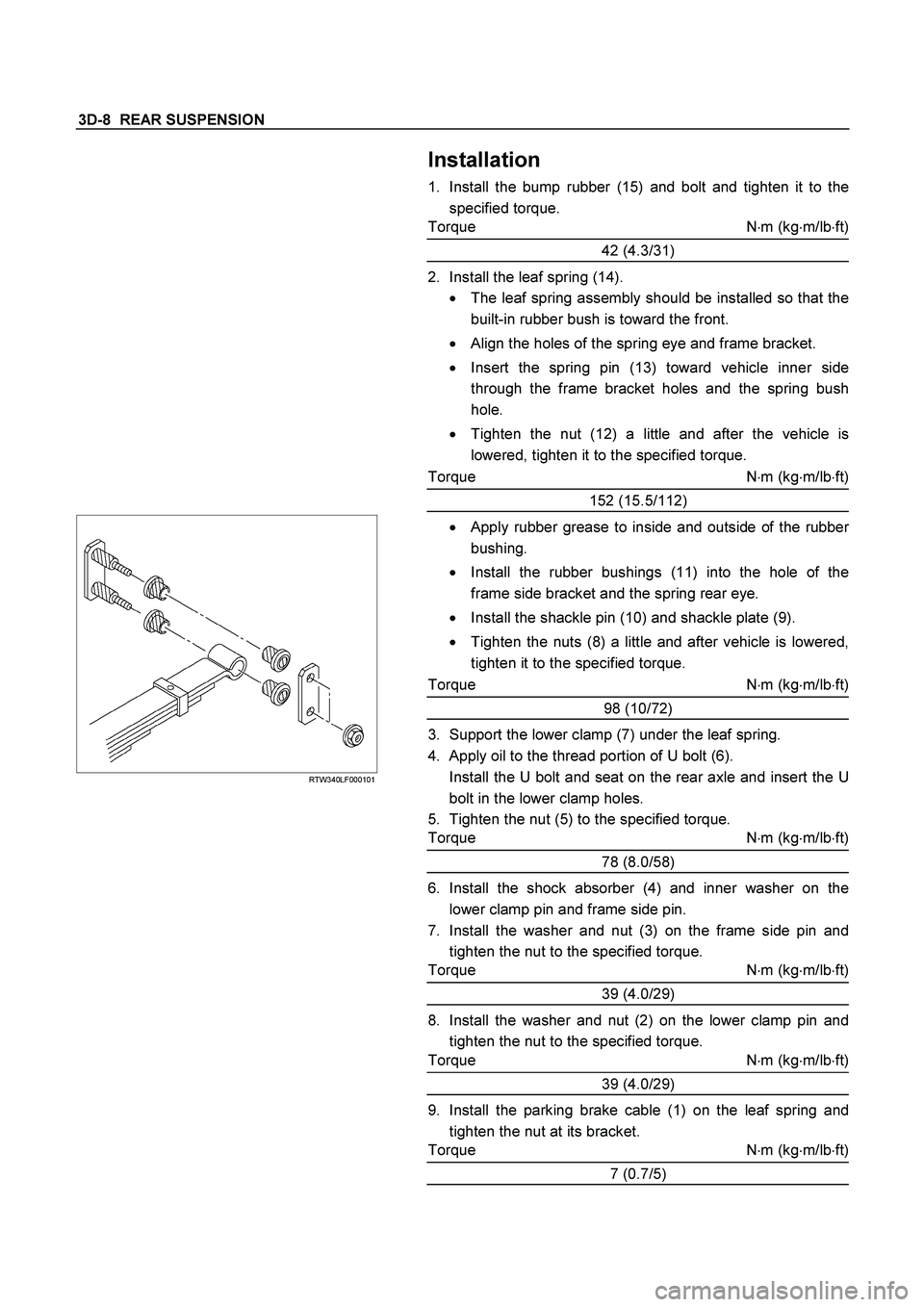
2. Install the leaf spring (14).
� The leaf spring assembly should be installed so that the
built-in rubber bush is toward the front.
� Align the holes of the spring eye and frame bracket.
� Insert the spring pin (13) toward vehicle inner side
through the frame bracket holes and the spring bush
hole.
� Tighten the nut (12) a little and after the vehicle is
lowered, tighten it to the specified torque.
Torque N
�m (kg
�m/lb
�ft)
152 (15.5/112)
RTW340LF000101
� Apply rubber grease to inside and outside of the rubber
bushing.
� Install the rubber bushings (11) into the hole of the
frame side bracket and the spring rear eye.
� Install the shackle pin (10) and shackle plate (9).
� Tighten the nuts (8) a little and after vehicle is lowered,
tighten it to the specified torque.
Torque N�m (kg�m/lb�ft)
98 (10/72)
3. Support the lower clamp (7) under the leaf spring.
4. Apply oil to the thread portion of U bolt (6).
Install the U bolt and seat on the rear axle and insert the U
bolt in the lower clamp holes.
5. Tighten the nut (5) to the specified torque.
Torque N�m (kg�m/lb�ft)
78 (8.0/58)
6. Install the shock absorber (4) and inner washer on the
lower clamp pin and frame side pin.
7. Install the washer and nut (3) on the frame side pin and
tighten the nut to the specified torque.
Torque N�m (kg�m/lb�ft)
39 (4.0/29)
8. Install the washer and nut (2) on the lower clamp pin and
tighten the nut to the specified torque.
Torque N�m (kg�m/lb�ft)
39 (4.0/29)
9. Install the parking brake cable (1) on the leaf spring and
tighten the nut at its bracket.
Torque N
�m (kg
�m/lb
�ft)
7 (0.7/5)
Page 3567 of 4264
REAR SUSPENSION 3D-11
TROUBLESHOOTING
1. BODY INCLINATION
Checkpoint Trouble Cause Countermeasure
ReplaceBushings worn or
disintegrated NG
Mounting brackets
Shock absorbers
ReplaceDefective
Spring brackets and U-bolts
Shackle pins and bushings
Replace
Retighten
Replace
Cracked
Bolt loosened
Worn or disintegrated
Regrease
Replace
Poorly lubricated
Weak or broken
OK OK
OK
NG NG NG NG NG NG
OKSpring
Page 3570 of 4264
3D-14 REAR SUSPENSION
3. SPRING BREAKAGE
Checkpoint Trouble Cause Countermeasure
Replace
Oil leakage
NG
Shock absorber
Replace
Bushing worn
U-bolts
Shackle pins and pivot pins
Replace
Retighten
Retighten
Damaged
Bolts and nuts for loosening
Bolts and nuts for loosening
Replace
Worn or damaged
OK
OK
NG
NG
NG
NG
NG
OK
Condition of loading
Continued on the next page
Page 3620 of 4264

7D-32 TRANSFER CASE
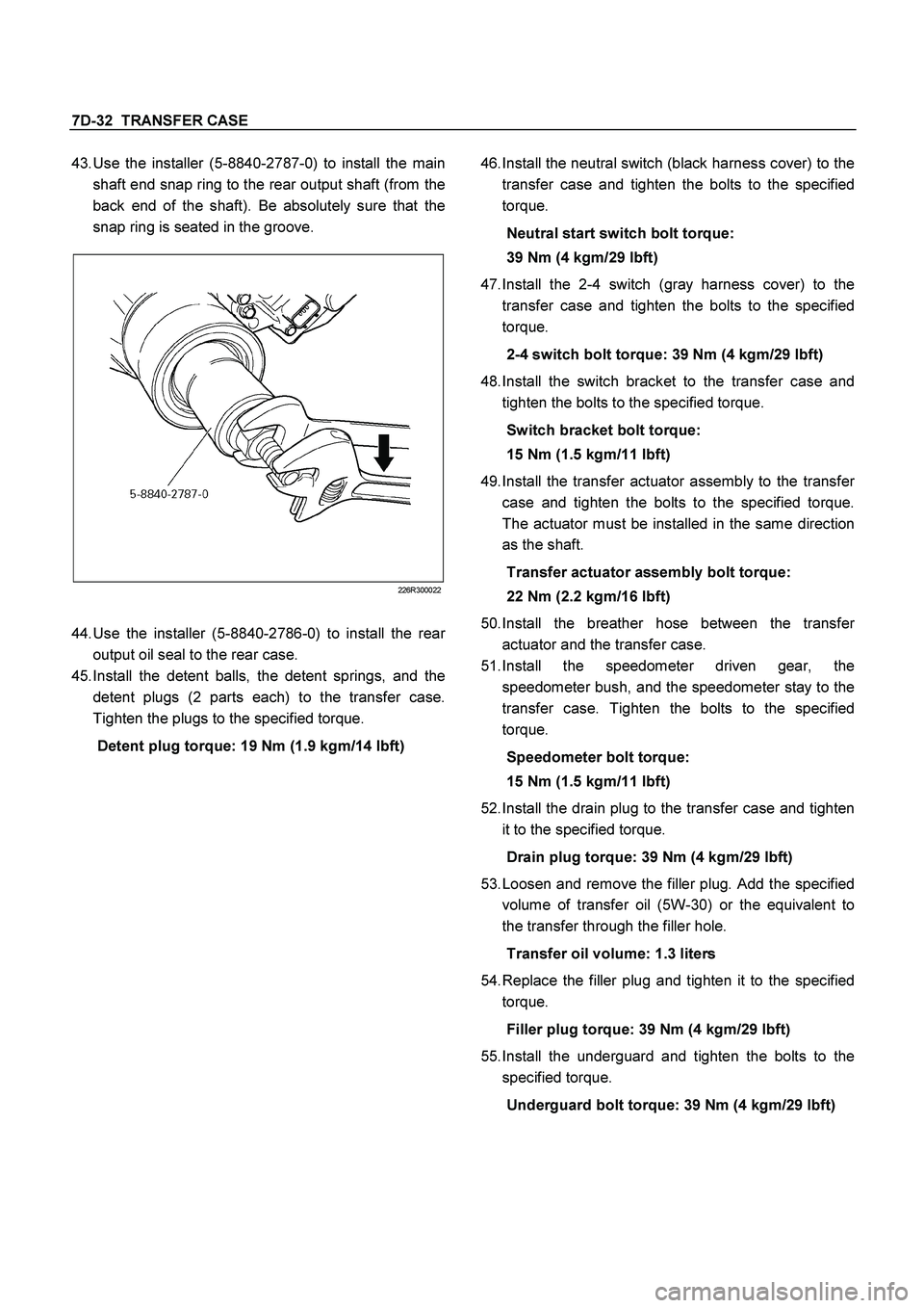
43.
Use the installer (5-8840-2787-0) to install the main
shaft end snap ring to the rear output shaft (from the
back end of the shaft). Be absolutely sure that the
snap ring is seated in the groove.
226R300022
44.
Use the installer (5-8840-2786-0) to install the rea
r
output oil seal to the rear case.
45.
Install the detent balls, the detent springs, and the
detent plugs (2 parts each) to the transfer case.
Tighten the plugs to the specified torque.
Detent plug torque: 19 Nm (1.9 kgm/14 lbft)
46.
Install the neutral switch (black harness cover) to the
transfer case and tighten the bolts to the specified
torque.
Neutral start switch bolt torque:
39 Nm (4 kgm/29 lbft)
47.
Install the 2-4 switch (gray harness cover) to the
transfer case and tighten the bolts to the specified
torque.
2-4 switch bolt torque: 39 Nm (4 kgm/29 lbft)
48.
Install the switch bracket to the transfer case and
tighten the bolts to the specified torque.
Switch bracket bolt torque:
15 Nm (1.5 kgm/11 lbft)
49.
Install the transfer actuator assembly to the transfe
r
case and tighten the bolts to the specified torque.
The actuator must be installed in the same direction
as the shaft.
Transfer actuator assembly bolt torque:
22 Nm (2.2 kgm/16 lbft)
50.
Install the breather hose between the transfe
r
actuator and the transfer case.
51.
Install the speedometer driven gear, the
speedometer bush, and the speedometer stay to the
transfer case. Tighten the bolts to the specified
torque.
Speedometer bolt torque:
15 Nm (1.5 kgm/11 lbft)
52.
Install the drain plug to the transfer case and tighten
it to the specified torque.
Drain plug torque: 39 Nm (4 kgm/29 lbft)
53.
Loosen and remove the filler plug. Add the specified
volume of transfer oil (5W-30) or the equivalent to
the transfer through the filler hole.
Transfer oil volume: 1.3 liters
54.
Replace the filler plug and tighten it to the specified
torque.
Filler plug torque: 39 Nm (4 kgm/29 lbft)
55.
Install the underguard and tighten the bolts to the
specified torque.
Underguard bolt torque: 39 Nm (4 kgm/29 lbft)
Page 3661 of 4264

TRANSFER CONTROL SYSTEM 7D1-35
3.
Shifting from 4H to 4L
3-1 When the 4L indicator flashes at 2Hz
When shifting from 4H to 4L, the 4L indicator continues flashing at 2Hz until shifting in the transfer case is
completed. The phases of the engaged splines may sometimes deviated preventing completion of shifting.
By correcting the deviation of phases, shifting is completed.
Step 3-1:
(In case of AT): Set the select bar of the transmission to the D position.
(In case of MT): Set the lever of the transmission to a position allowing running and engage the clutch
gently.
At this time, some rotating force acts on the engaged splines, phase is corrected and the engagement is
completed.
3-2 When the 4L indicator flashes at 2Hz for 10 seconds and then keeps ON again (AT vehicle)
This condition occurs when torsional torque has been generated between the transmission and road surface
and the transfer standby mechanism cannot absorb it completely.
Step 3-2:
Set the select lever of the transmission to the N position. (Stepping on the brake pedal is effective at
this time.)
3-3 When the 4L indicator flashes at a frequency of 4Hz
Shifting from 4H to 4L is restricted.
When the vehicle is running, the transmission lever is at the running range and the engine speed is high (L4:
3000rpm or more V6: 2000rpm), the transfer cannot be shifted from 4H to 4L (restriction on operation).
Restriction on operation (Except 4JA1-LT)
The 4H, neutral and 4L shifting mechanism has no synchronization function. Therefore, if relative rotations in the
mechanism become excessive, shifting exerts adverse influence on the internal mechanism of the transfer. To
avoid such a trouble, vehicle condition is detected to restrict the operation (vehicle speed, engine speed and TM
position).
Requirement to restrict the speed: Vehicle should be in stop.
For the reason of the detection logic, time to wait for start of operation may be required.
A/T: If the vehicle is in stop for a long time at the TM running range (D, 1, 2) before operating the AT, waiting
time becomes longer (from 1 second to 3 minutes at the maximum).
M/T: If the vehicle is at stop with the clutch stepped on at the T/M running position (1 – R), the time to wait
becomes longer.
Waiting time means the time commencing from when other requirements (engine speed and T/M position) are
met to permission of the speed restriction. Operation during the waiting time is not permissible.
The waiting time is 1 second at the minimum and increases up to 5 seconds if the above condition continues 3
minutes. After that, the waiting time increases up to 3 minutes in 2 minutes.
When it is clear that the above condition has continued and reduction of waiting time is desirable, turn on or off
the ignition or start and stop the vehicle several meters.
Requirements for permission of restriction on engine speed: Engine speed should be decreased.
The engine speed of 3000rpm (V6: 2000rpm) or below is advisable.
Requirements for permission of restriction on T/M position restriction:
(AT) N range is recommendable
(MT) should be at the neutral.
These requirements for permission should be all met before the switch is operated. If the requirements are met
after operation, operation is not automatically effected but re-operation is required after permission is given.