Page 3536 of 4264
3C-44 FRONT SUSPENSION
Lower Control Arm
Lower Control Arm and Associated Parts
RTW33CLF000201
Legend
(1) Cam Bolt
(2)Bush, Front
(3) Cam Plate and Nut
(4) Nut, Rear
(5) Bush, Rear
(6) Bolt, Rear
(7) Bolt, Lower Ball Joint
(8) Bolt, Torsion Bar Arm
(9) Torsion Bar Arm Bracket and Nut
(10) Torsion Bar
(11) Lower Control Arm
(12) Lower Ball Joint and Nut
(13) Shock Absorber, Bolt and Nut
(14) Stabilizer Link and Nut
Page 3537 of 4264

FRONT SUSPENSION 3C-45
Removal
1. Raise the vehicle and support the frame with
suitable safety stands.
2. Remove wheel and tire assembly. Refer to Wheel
in this section.
3. Remove the tie-rod end from the knuckle. Refer to
Power Steering Unit in Steering section.
4. Remove the retaining ring from the front axle
driving shaft to release the shaft from hub. Refer to
Front Hub and Disc in Driveline/Axle section.
5. Support lower control arm with a jack.
6. Remove cam plate and nut.
7. Remove rear nut.
8. Remove torsion bar, refer to Torsion Bar in this
section.
9. Remove torsion bar arm bracket.
10. Disconnect the stabilizer link at the lower control
arm.
11. Remove the shock absorber lower end from the
lower control arm.
12. Remove the lower ball joint from the lower control
arm.
13. Remove cam bolt.
14. Remove rear bolt.
15. Remove lower control arm.
16. Remove torsion bar arm bolt.
17. Remove lower ball joint bolt.
18. Remove front bushing by using remover 5-8840-
2123-0.
Front
901RW154
Front
901RW155
19. Remove rear bushing by using remover 5-8840-
2124-0.
Front
901RW051
Front
901RW052
Page 3538 of 4264

3C-46 FRONT SUSPENSION
Inspection and Repair
Make necessary correction or parts replacement if
wear, damage, corrosion or any other abnormal
condition are found through inspection.
Check the following parts:
�
Lower control arm
�
Bushing
Installation
1. Install rear bushing by using installer 5-8840-2124-
0.
Front
901RW053
2. Install front bushing by using installer 5-8840-
2123-0.
Front
901RW156
3. Install lower ball joint bolt.
4. Install torsion bar arm bolt.
5. Install lower control arm.
6. Install rear bolt.
7. Install cam bolt the hole and projection are
upward.
8. Install lower ball joint and tighten it to the specified
torque (12).
Torque: 127 N�
�� �m (12.9kg�
�� �m/94 lb ft)
9. Install shock absorber and tighten it to the
specified torque (13).
Torque: 93 N�
�� �m (9.5kg�
�� �m/69 lb ft)
10. Install stabilizer link and tighten it to the specified
torque (14).
Torque: 50 N�
�� �m (5.1kg�
�� �m/37 lb ft)
11. Install torsion bar arm bracket and tighten it to the
specified torque.
Torque: 116 N
�
�� �m (11.8kg
�
�� �m/85 lb ft)
12. Install Torsion bar, refer to Torsion Bar in this
section.
13. Install rear nut and tighten lower link nut finger-
tight (4).
NOTE: Apply oil to the thread.
NOTE: Tighten the nut or bolt with the parts in the
position shown in the illustration below.
Buffer clearance: 29.7 mm (1.17 in)
Torque: 235 N�
�� �m (24.0kg�
�� �m/174 lb ft)
450R100002
Page 3546 of 4264

3C-54 FRONT SUSPENSION
TROUBLESHOOTING
1. VIBRATION, SHOCK, AND SHIMMY OF STEERING WHEEL
Checkpoint Trouble Cause Countermeasure
Check front axle
Check wheel alignment
Check suspension ball joint
Check shock absorber or
attaching nut and bolt
Replace
Adjust
Replace
Replace or retighten
Check steering unit and
linkage
Faulty
Worn
Malfunction or loose
Check upper and lower link
bushings
Replace
Adjust
Worn
Incorrect
OK OK OK
NG NG NG NG NG NG
OK OK
Check vehicle trim height
�
Improperly adjusted or worn front
wheel bearing.
�
Worn or incorrectl
y adjusted wheel
bearing.
Replace; refer to Section 4C "Front
Wheel Drive"
�
Insufficientl
y tightened steeringgear housing.
�
Wear of steering linkage.
�
Excessive backlash due to
improper ad
justment of the steeringgear box.
� Worn column bearing weakened
column bearing spring, or loose
clamp.
Replace; refer to Section 3B
"Steering"
�
Improper tire pressure.
� Imbalance and deformation of frond
wheel.
�
Unevenl
y worn tire or insufficient
tightening of wheel nuts.
Replace; refer to Section 3E "Wheel
and Tires"
Page 3551 of 4264
FRONT SUSPENSION 3C-59
5. NOISES
Checkpoint Trouble Cause Countermeasure
Lubricating oil and grease for
upper and lower ball joint
Shock absorber
Stabilizer fixing nuts and bolts
Upper and lower links
bushings
Replace
Replace
Retighten
Replace
Insufficient
Faulty
Loose
Worn
Shock absorber fixing nut and
bolt
Retighten
Loose
Continued on the next pageOK OK OK OK
NG NG NG NG NG
OK
Upper and lower ball joint
Replace
Damaged
NG
Page 3557 of 4264

REAR SUSPENSION 3D-1
SECTION 3D
REAR SUSPENSION
TABLE OF CONTENTS
PAGE
Main Data and Specifications...........................................................................................3D- 2
Torque Specifications........................................................................................................ 3D- 3
Rear Suspension................................................................................................................3D- 4
General Description ...................................................................................................... 3D- 4
Leaf Spring and Shock Absorber ..................................................................................... 3D- 5
Leaf Spring and Associated Parts ............................................................................... 3D- 5
Removal .........................................................................................................................3D- 6
Inspection and Repair ................................................................................................... 3D- 7
Installation ..................................................................................................................... 3D- 8
Leaf Spring Assembly ....................................................................................................... 3D- 9
Disassembly .................................................................................................................. 3D- 9
Inspection and Repair ................................................................................................... 3D- 9
Reassembly ................................................................................................................... 3D- 10
Troubleshooting................................................................................................................. 3D- 11
Page 3558 of 4264
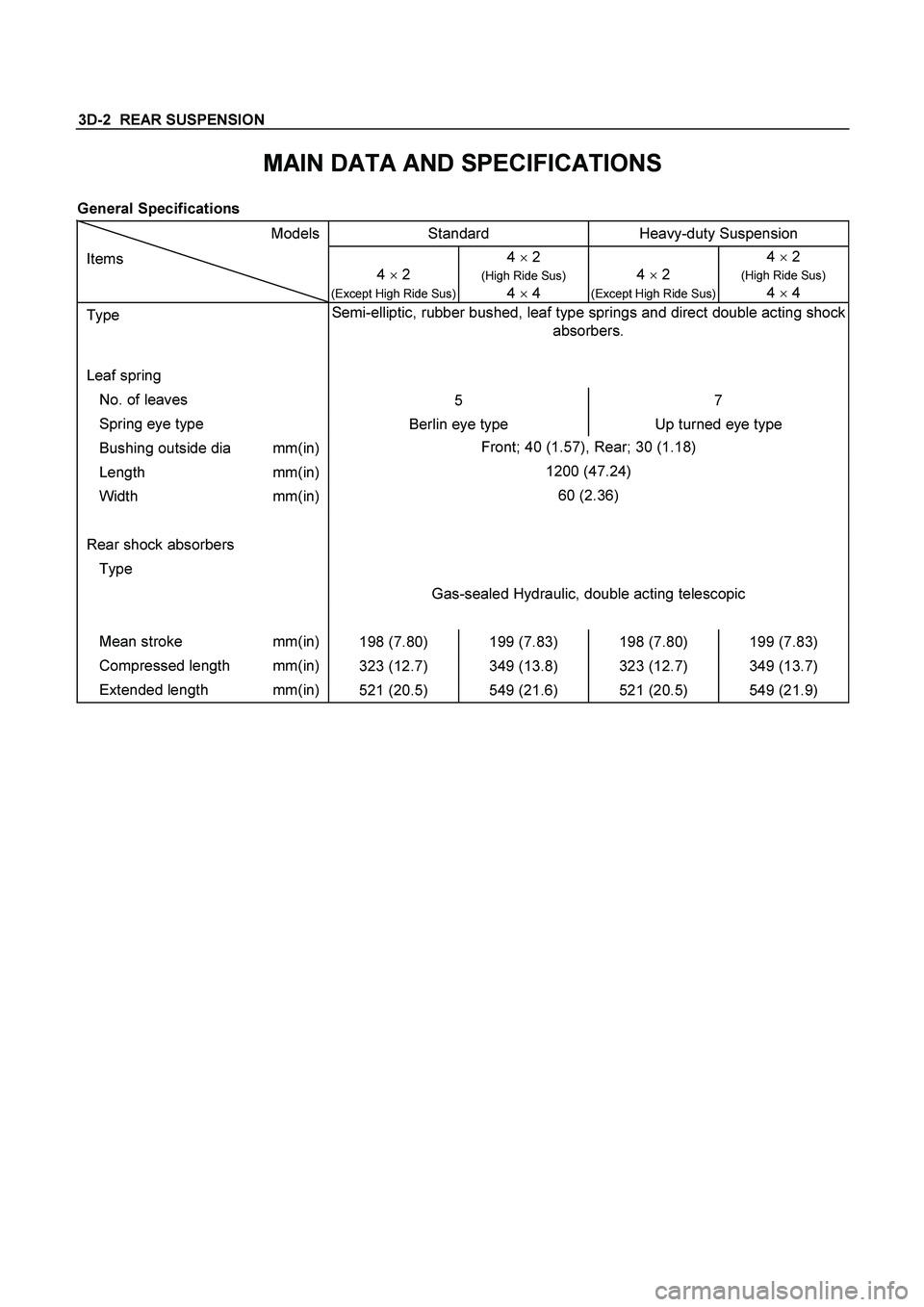
3D-2 REAR SUSPENSION
MAIN DATA AND SPECIFICATIONS
General Specifications
Models Standard Heavy-duty Suspension
Items
4 � 2
(Except High Ride Sus)
4 � 2
(High Ride Sus)
4
� 4
4 � 2 (Except High Ride Sus) 4 � 2
(High Ride Sus)
4
� 4
Type Semi-elliptic, rubber bushed, leaf type springs and direct double acting shock
absorbers.
Leaf spring
No. of leaves
5 7
Spring eye type
Berlin eye type Up turned eye type
Bushing outside dia mm(in) Front; 40 (1.57), Rear; 30 (1.18)
Length mm(in) 1200 (47.24)
Width mm(in) 60 (2.36)
Rear shock absorbers
Type
Gas-sealed Hydraulic, double acting telescopic
Mean stroke mm(in)
198 (7.80) 199 (7.83) 198 (7.80) 199 (7.83)
Compressed length mm(in)
323 (12.7) 349 (13.8) 323 (12.7) 349 (13.7)
Extended length mm(in)
521 (20.5) 549 (21.6) 521 (20.5) 549 (21.9)
Page 3560 of 4264
3D-4 REAR SUSPENSION
REAR SUSPENSION
GENERAL DESCRIPTION
Rear suspension absorbs vibration from the road surface thus preventing vehicle damage, as well as providing a
good ride.
Components parts
� Spring between the body and the axle case
� Spring shackle connecting the spring to the body
� Clamp and U-bolt fixing the axle case to the spring
� Shock absorber as a countermeasure for vibration
 Cam Bolt
(2)Bush, Front
(3) Cam Plate and Nut
(4) Nut, Rear
(5) Bush, Rear")