Page 1183 of 4264
ENGINE MECHANICAL 6A – 43
ENGINE OVERHAUL
REMOVAL
EXTERNAL PARTS
RTW36AMF000401
Removal Steps
1. Clutch Assembly or Flex Plate
2. Intake Pipe and Throttle Body
3-1. EGR Pipe
3-2. EGR cooler (EURO III model only)
4. EGR Valve
5. Oil Level Gauge
6. Fuel Filter Assembly (Except EURO III)
7. Fuel Filter Bracket (Except EURO III)
8. Fuel Injection Pipe with Clip
9. Power Steering Oil Pump Bracket
10. Intake Manifold
11. Engine Mounting Bracket and Foot
12. Injection Pump Cover
13. Injection Pump
14. Starter Motor
15. Oil Pressure Warning Switch
16. Fuel Leak Off Pipe
17. Oil Cooler Water Pipe
18. Cooling Fan Pulley
19. Heat Protector
20. Catalytic Converter
21. Turbocharger
22. Compressor Bracket
23. Vacuum Pump Oil Return Hose
24. Generator and Adjusting Plate
25. Water Inlet Pipe
26. Generator Bracket
27. Oil Cooler with Oil Filter
28. Exhaust Manifold
Page 1185 of 4264

ENGINE MECHANICAL 6A – 45
4JA1�L
RTW46ASH001001
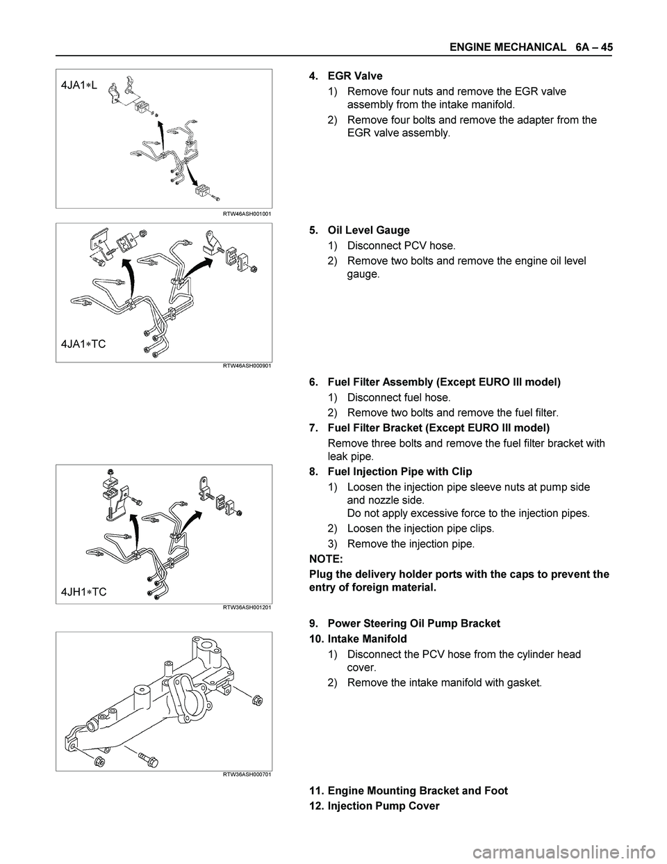
4. EGR Valve
1) Remove four nuts and remove the EGR valve
assembly from the intake manifold.
2) Remove four bolts and remove the adapter from the
EGR valve assembly.
4JA1�TC RTW46ASH000901
5. Oil Level Gauge
1) Disconnect PCV hose.
2) Remove two bolts and remove the engine oil level
gauge.
6. Fuel Filter Assembly (Except EURO III model)
1) Disconnect fuel hose.
2) Remove two bolts and remove the fuel filter.
7. Fuel Filter Bracket (Except EURO III model)
Remove three bolts and remove the fuel filter bracket with
leak pipe.
4JH1�TC RTW36ASH001201
8. Fuel Injection Pipe with Clip
1) Loosen the injection pipe sleeve nuts at pump side
and nozzle side.
Do not apply excessive force to the injection pipes.
2) Loosen the injection pipe clips.
3) Remove the injection pipe.
NOTE:
Plug the delivery holder ports with the caps to prevent the
entry of foreign material.
9. Power Steering Oil Pump Bracket
RTW36ASH000701
10. Intake Manifold
1) Disconnect the PCV hose from the cylinder head
cover.
2) Remove the intake manifold with gasket.
11. Engine Mounting Bracket and Foot
12. Injection Pump Cover
Page 1186 of 4264
6A – 46 ENGINE MECHANICAL
13. Injection Pump
Rrefer to secton 6C-19 (Injection Iump)
14. Starter Motor
15. Oil Pressure Warning Switch
16. Fuel Leak Off Pipe
17. Oil Cooler Water Pipe
18. Cooling Fan Pulley
19. Heat Protector
20. Catalytic Converter
21. Turbocharger
1) Disconnect the water hose between thermostat
housing cover and turbocharger.
2) Disconnect the water hose between water inlet pipe
and turbocharger.
3) Remove the oil feed pipe.
4) Remove the oil return pipe.
5) Remove the turbocharger and the gasket.
NOTE:
Plug the turbocharger body oil ports and water ports after
removing the turbocharger assembly to prevent the entry
of foreign material.
22. Compressor Bracket
23. Vacuum Pump Oil Return Hose
24. Generator and Adjusting Plate
25. Water Inlet Pipe
26. Generator Bracket
27. Oil Cooler with Oil Filter
28. Exhaust Manifold
027R100007
037RY00001
Page 1258 of 4264
6A – 118 ENGINE MECHANICAL
INSTALLATION
EXTERNAL PARTS
RTW36AMF000701
Installation Steps
1.
Exhaust Manifold 18. Engine Mounting Bracket and
2.
Oil Cooler with Oil Filter Foot
3. Generator Bracket 19. Intake Manifold
4. Water Inlet Pipe 20. Power Steering Oil Pump
5.
Generator and Adjusting Plate Bracket
6.
Vacuum Pump Oil Return Hose 21. Fuel Injection Pipe with Clip
7.
Compressor Bracket 22. Fuel Filter Bracket (Except
EURO III)
8. Turbocharger 23. Fuel Filter Assembly (Except
EURO III)
9. Catalytic Converter 24. Oil Level Gauge
10. Heat Protector 25. EGR Valve
11. Cooling Fan Pulley 26-1. EGR Pipe
12. Oil Cooler Water Pipe 26-2. EGR Cooler (EURO III model
only)
13. Fuel Leak Off Pipe 27. Intake Pipe and Throttle Body
(4JA1TC/4JH1TC only)
14. Oil Pressure Warning Switch 28. Clutch Assembly or Flex Plate
15. Starter Motor
16. Injection Pump
17. Injection Pump Cover
Page 1259 of 4264
ENGINE MECHANICAL 6A – 119
Installation
1. Exhaust Manifold
1) Install the exhaust manifold to the cylinder head with
the manifold gasket.
2) Tighten the exhaust manifold bolts and nuts to the
specified torque a little at a time.
Exhaust Manifold Bolt and Nuts
Torque N·m(kg·m/Ib ft)
27 (2.7/20)
3) Install the exhaust manifold bracket to the manifold
and the cylinder body.
Manifold Bracket Bolt Torque N·m(kg·m/Ib ft)
19 (1.9/14)
RTW46ASH001301
2. Oil Cooler with Oil Filter
1) Install the O-ring to the oil filter body flange groove.
2) Install the oil filter body to cylinder block and tighten to
the specified torque.
Oil Filter Body Bolt and Nut
Torque N·m(kg·m/Ib ft)
BOLT 19 (1.9/14)
NUT 24 (2.4/17)
3. Generator Bracket
Install the generator bracket to the cylinder body and
tighten the bracket bolts to the specified torque.
Bracket Bolt Torque N·m(kg·m/Ib ft)
40 (4.1/30)
027R100003
027R100004
066RY00001
Page 1264 of 4264

6A – 124 ENGINE MECHANICAL
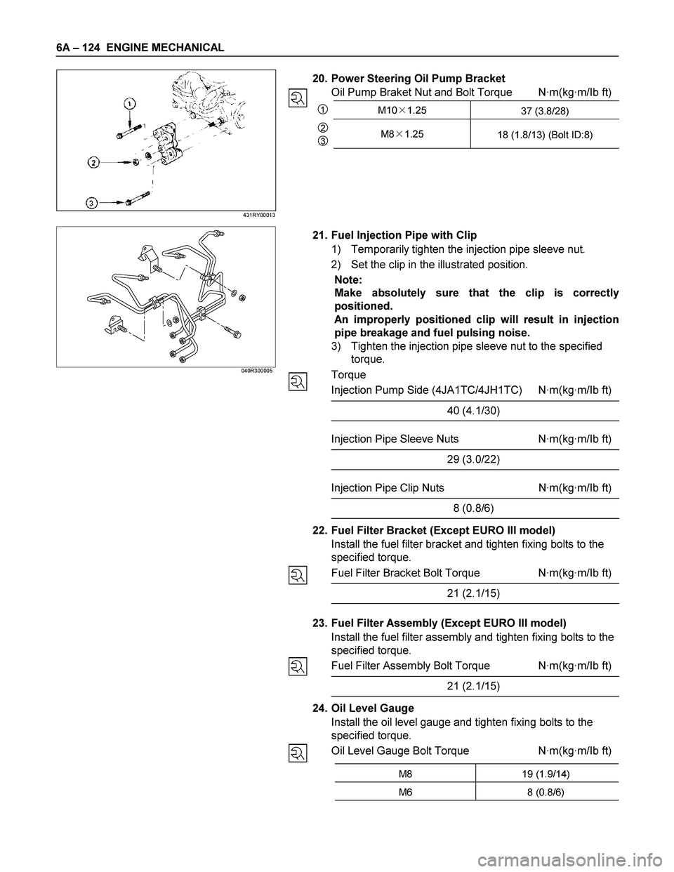
20. Power Steering Oil Pump Bracket
Oil Pump Braket Nut and Bolt Torque N·m(kg·m/Ib ft)
1M10�1.25
37 (3.8/28)
2
3M8�1.25
18 (1.8/13) (Bolt ID:8)
040R300005
21. Fuel Injection Pipe with Clip
1) Temporarily tighten the injection pipe sleeve nut.
2) Set the clip in the illustrated position.
Note:
Make absolutely sure that the clip is correctly
positioned.
An improperly positioned clip will result in injection
pipe breakage and fuel pulsing noise.
3) Tighten the injection pipe sleeve nut to the specified
torque.
Torque
Injection Pump Side (4JA1TC/4JH1TC) N·m(kg·m/Ib ft)
40 (4.1/30)
Injection Pipe Sleeve Nuts N·m(kg·m/Ib ft)
29 (3.0/22)
Injection Pipe Clip Nuts N·m(kg·m/Ib ft)
8 (0.8/6)
22. Fuel Filter Bracket (Except EURO III model)
Install the fuel filter bracket and tighten fixing bolts to the
specified torque.
Fuel Filter Bracket Bolt Torque N·m(kg·m/Ib ft)
21 (2.1/15)
23. Fuel Filter Assembly (Except EURO III model)
Install the fuel filter assembly and tighten fixing bolts to the
specified torque.
Fuel Filter Assembly Bolt Torque N·m(kg·m/Ib ft)
21 (2.1/15)
24. Oil Level Gauge
Install the oil level gauge and tighten fixing bolts to the
specified torque.
Oil Level Gauge Bolt Torque N·m(kg·m/Ib ft)
M8 19 (1.9/14)
M6 8 (0.8/6)
431RY00013
Page 1266 of 4264
6A – 126 ENGINE MECHANICAL
LUBRICATION SYSTEM
LUBRICATING OIL FLOW
1. Oil Pump Relief Valve Operating Pressure: 6.2 - 7.8kg/cm 2 (608 - 764Kpa)
2. Regulating Valve Operating Pressure: 5.7 - 6.3kg/cm 2 (558.6 - 617.4Kpa)
3. Oil Cooler Relief Valve Opening Pressure: 2.8 - 3.4kg/cm 2 (270 - 330Kpa)
4. Oil Filter Relief Valve Opening Pressure: 0.8 - 1.2kg/cm 2 (78.4 - 117.6Kpa)
5. Oil Pressure Switch Operating Pressure: 0.3 - 0.5kg/cm 2 (29.4 - 49.0Kpa)
6. Regulating Valve: 1.8 - 2.2kg/cm 2 (176 - 216Kpa)
The 4J series engine has a full flow type lubricating system.
Lubricating oil is pumped from the oil pump to the cylinder body oil gallery through the oil cooler and the oil filter. It is
then delivered to the vital parts of the engine from the cylinder body oil gallery.
Oiling jets installed on the cylinder body spray engine oil to the piston backside faces to achieve maximum piston
cooling effect.
Page 1267 of 4264
ENGINE MECHANICAL 6A – 127
OIL PUMP AND OIL FILTER
RTW46ALF001501
The 4J series engine is equipped with a gear type oil pump.
The oil filter and the water cooled oil cooler integrated a single unit to increase the cooling effect.