Page 2548 of 4264
6D1-6 ENGINE ELECTRICAL
1
5
3 42
Removal
1. Remove negative cable (1).
2. Remove positive cable (2).
3. Remove retainer screw and rods (3).
4. Remove retainer (4).
5. Remove battery (5).
Installation
1. Install battery.
2. Install retainer.
3. Instal retainer screw and rods.
NOTE: Make sure that the rod is hooked on the body side.
4. Install positive cable.
5. Install negative cable.
Main Data and Specifications
General Specifications
Model (JIS) 34B19L 50D20L
Voltage (V) 12 12
Cold Cranking Performance (Amp) 272 306
Reserve Capacity (Min) 49 78
Page 2550 of 4264

6D2-2 IGNITION SYSTEM
General Description
Ignition is done by the Ignition Module that fires.
Since the cylinder on exhaust stroke requires less energy to
fire its spark plug, energy from the ignition coils can be utilized
to fire the mating cylinder on compression stroke.
A notch in the timing disc on the crankshaft activates the crank
angle sensor which then sends information such as firing order
and starting timing of ignition coil to the ECM.
By receiving signals such as crank position, engine speed,
water temperature and Manifold Absolute Pressure (MAP), the
ECM controls the ignition timing.
Service Precaution
CAUTION:
Always use the correct fastener in the proper location.
When you replace a fastener, use ONLY the exact part
number for that application. ISUZU will call out those
fasteners that require a replacement after removal. ISUZU
will also call out the fasteners that require thread lockers
or thread sealant. UNLESS OTHERWISE SPECIFIED, do
not use supplemental coatings (Paints, greases, or other
corrosion inhibitors) on threaded fasteners or fastener
joint interfaces. Generally, such coatings adversely affect
the fastener torque and the joint clamping force, and may
damage the fastener. When you install fasteners, use the
correct tightening sequence and specifications. Following
these instructions can help you avoid damage to parts
and systems.
Diagnosis
Refer to Section Drivability and Emissions for the diagnosis to
electronic ignition system (El system).
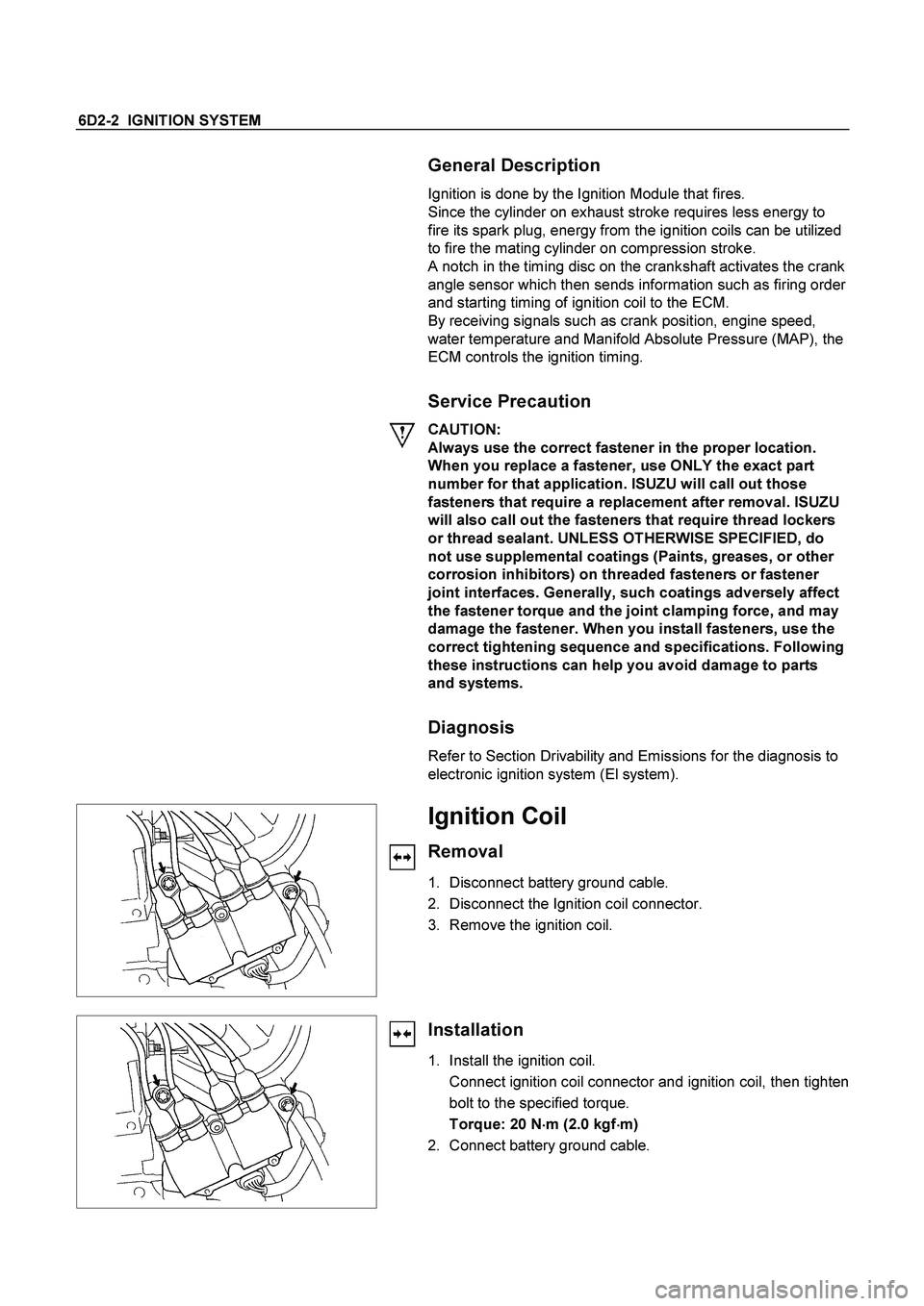
Ignition Coil
Removal
1. Disconnect battery ground cable.
2. Disconnect the Ignition coil connector.
3. Remove the ignition coil.
Installation
1. Install the ignition coil.
Connect ignition coil connector and ignition coil, then tighten
bolt to the specified torque.
Torque: 20 N�
�� �m (2.0 kgf�
�� �m)
2. Connect battery ground cable.
Page 2551 of 4264

IGNITION SYSTEM 6D2-3
Spark Plug
Removal
1. Remove spark plugs.
Inspection and Repair
The spark plug affects entire engine performance and
therefore its inspection is very important.
�
Check electrode and insulator for presence of cracks, and
replace if any.
�
Check electrode for wear, and replace if necessary.
�
Check gasket for damage, and replace if necessary.
�
Measure insulation resistance with an ohmmeter, and
replace if faulty.
� Adjust spark plug gap to 1.0 - 1.1 mm (0.027 in) - 0.8 mm
(0.031 in).
�
Check fuel and electrical systems if spark plug is extremel
y
dirty.
�
Use spark plugs having low heat value (hot type plug) if fuel
and electrical systems are normal.
�
Use spark plugs having high heat value (cold type plug) i
f
insulator and electrode are extremely burned.
Sooty Spark Plugs
Much deposit of carbon or oil on the electrode and insulator of
spark plug reduces the engine performance.
Possible causes:
� Too rich mixture
�
Presence of oil in combustion chamber
�
Incorrectly adjusted spark plug gap
Burning Electrodes
This fault is characterized by scorched or heavily oxidized
electrode or blistered insulator nose.
Possible causes:
�
Too lean mixture
�
Improper heat value
Measuring Insulation Resistance
�
Measure insulation resistance using a 500 volt megaohm
meter.
� Replace spark plugs if measured value is out of standard.
Insulation resistance: 50 M
�
�� � or more
Page 2552 of 4264
6D2-4 IGNITION SYSTEM
Cleaning Spark Plugs
�
Clean spark plugs with a spark plug cleaner.
� Raise the ground electrode to an angle of 45 to 60 degrees.
if electrode is wet, dry it gefore cleaning.
�
After spark plug is thoroughly cleaned, check insulator for
presence of cracks.
�
Clean threads and metal body with a wire brush.
�
File the electrode tip if electrode is extremely worn.
�
Bend the ground electrode to adjust the spark plug gap.
Installation
1. Spark plugs
�
Tighten spark plugs to the specified torque.
Torque: 25 N
�
�� �m (2.5 kgf
�
�� �m)
Crankshaft Angle Sensor
Removal
1. Disconnect battery ground cable
2. Disconnect the wiring connector from crankshaft angle
sensor.
3. Remove crankshaft angle sensor from cylinder block.
Installation
1. Install crankshaft angle sensor into the cylinder block.
Before installation, apply small amount of engine oil to the
O-ring.
Torque: 6 N
�
�� �m (0.6 kgf
�
�� �m)
2. Reconnect wiring connector to crankshaft angle sensor.
Page 2553 of 4264
IGNITION SYSTEM 6D2-5
Main Data and Specifications
General Specifications
Ignition System
Ignition Form Electronic Ignition System (El system) with Crankshaft angle Sensor
Spark Plug
Type
No. of Coils and Type
Coil Location
Torque Electronic Spark Control
2 Solid State
Engine-mounted
20 N�m (2.0 kgf�m)
Page 2556 of 4264

6D3-2 STARTING AND CHARGING SYSTEM
Starting System
General Description
Cranking Circuit
The cranking system consists of a battery, starter, starter
switch, starter relay, etc. These main components are
connected.
Starter
The cranking system employs a magnetic type reduction
starter in which the motor shaft is also used as a pinion shaft.
When the starter switch is turned on, the contacts of magnetic
switch are closed, and the armature rotates. At the same time,
the plunger is attracted, and the pinion is pushed forward by
the shift lever to mesh with the ring gear.
Then, the ring gear runs to start the engine. When the engine
starts and the starter switch is turned off, the plunger returns,
the pinion is disengaged from the ring gear, and the armature
stops rotation. When the engine speed is higher than the
pinion, the pinion idles, so that the armature is not driven.
Service Precaution
CAUTION:
Always use the correct fastener in the proper location.
When you replace a fastener, use ONLY the exact part
number for that application. ISUZU will call out those
fasteners that require a replacement after removal. ISUZU
will also call out the fasteners that require thread lockers
or thread sealant. UNLESS OTHERWISE SPECIFIED, do
not use supplemental coatings (Paints, greases, or other
corrosion inhibitors) on threaded fasteners or fastener
joint interfaces. Generally, such coatings adversely affect
the fastener torque and the joint clamping force, and may
damage the fastener. When you install fasteners, use the
correct tightening sequence and specifications. Following
these instructions can help you avoid damage to parts
and systems.
Diagnosis
Condition Possible cause Correction
Starter does not run Charging failure Repair charging system
Battery Failure Replace Battery
Terminal connection failure Repair or replace terminal connector
and/or wiring harness
Starter switch failure Repair or replace starter switch
Starter failure Repair or replace starter
Page 2562 of 4264

6D3-8 STARTING AND CHARGING SYSTEM
General On-Vehicle Inspection
The operating condition of charging system is indicated by the
charge warning lamp. The warning lamp comes on when the
starter switch is turned to "ON" position. The charging system
operates normally if the lamp goes off when the engine starts.
If the warning lamp shows abnormality or if undercharged or
overcharged battery condition is suspected, perform diagnosis
by checking the charging system as follows:
1. Check visually the belt and wiring connector.
2. With the engine stopped, turn the stator switch to "ON"
position and observe the warning lamp.
If lamp does not come on:
Disconnect wiring connector from generator, and ground
the terminal "L" on connector side.
If lamp comes on:
Repair or replace the generator.
Generator
Removal
1. Disconnect battery ground cable.
2. Move drive belt tensioner to loose side using wrench then
remove drive belt.
3. Disconnect terminal "B" wiring connector and connector.
4. Remove generator assembly.
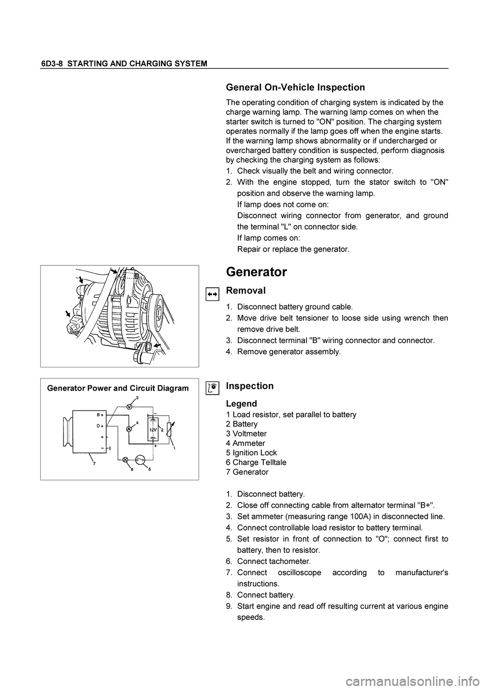
Generator Power and Circuit Diagram
Inspection
Legend
1 Load resistor, set parallel to battery
2 Battery
3 Voltmeter
4 Ammeter
5 Ignition Lock
6 Charge Telltale
7 Generator
1. Disconnect battery.
2. Close off connecting cable from alternator terminal "B+".
3. Set ammeter (measuring range 100A) in disconnected line.
4. Connect controllable load resistor to battery terminal.
5. Set resistor in front of connection to "O"; connect first to
battery, then to resistor.
6. Connect tachometer.
7. Connect oscilloscope according to manufacturer's
instructions.
8. Connect battery.
9. Start engine and read off resulting current at various engine
speeds.
Page 2565 of 4264

STARTING AND CHARGING SYSTEM 6D3-11
Warning
Do not reverse S and L connections as this will destroy the
warning lamp circuit of the regulator.
Ensure good electrical contact beween generator earth and
battery negative,
Operation
With the Iginiton switch turnded "ON", current is supplied via
the warning lamp to the "L" terminal of the regulator. Base
current is fed to T15 causing it to turn on, current then flows
from B+ through the rotor winding via the regulator brushes
and the collector emitter junction of T15 to earth completing
the circuit. The current in the rotor causes a magnetic field
between adjacent poles to be created, this field is rotated and
cuts the windings of the stator at right angles inducing a
voltage into them.
As the speed is increased this induced voltage increases and
results in curent being rectified in the 3 phase diode bridge and
supplied as DC to the B+ output and hence to the battery.
When the voltage at the B+ terminal of the battery reaches
around 14.2 volts, this voltage is monitored by the "S" lead and
turns the regulator Hybrid base current to T15 OFF removing
rotor current, resulting in a decrease in output voltage to below
the regulating voltage, T15 base current turns ON and the
whole cycle is repeated very rapidly.
D38 protects T15 and the regulator against the back voltage
developed across the rotor winding when T15 turns OFF.
The new generated EP regulators incorporate current limiting
in the warning lamp circuit.
Backup Regulation
The EP regulator will limit the output voltage to a safe level
should either the main B+ cable or the battery sense wire
become decoupled, the output voltage will be slightly above the
normal setting(1-3 volts).
Start up phase
When the Iginition switch is turned on and the engine is not
running, the current to the rotor is reduced by switching it on
and off at a 50% duty cycle, the frequency is approximately 4
KHz and may be audible at times.
This is quite normal, once the engine is started normal
regulation commences.
Warning lamp failure
Should the warning lamp fail, the generator will self excite by
deriving a small current from the phase connecion allowing the
voltage to build up to regulating level.
Note: no filed current will flow when the engine is cranking.