Page 2492 of 4264

FUEL INJECTOR
Removal
Caution: To reduce the risk of fire and personal injury, it is
necessary to relieve the fuel system pressure before
servicing the fue")
6A-72 ENGINE MECHANICAL (C24SE)
FUEL INJECTOR
Removal
Caution: To reduce the risk of fire and personal injury, it is
necessary to relieve the fuel system pressure before
servicing the fuel system components.
Caution: After relieving the fuel system pressure, a small
amount of fuel may be released when servicing fuel lines
or connections. Reduce the chance of personal injury by
covering the fuel line fitting with a shop towel before
disconnecting the fittings. The towel will absorb any fuel
that may leak out. When the disconnect is completed,
place the towel in an approved container.
1. Depressurize the fuel system.
2. Disconnect the fuel inlet.
3. Disconnect the fuel return line.
4. Remove the fuel rail from the intake manifold.
5. Remove the fuel injector from the fuel rail by disengaging
claws.
Installation
1. Install the fuel injector to the fuel rail by engaging claws.
2. Install the fuel rail to the intake manifold.
3. Connect the fuel return line firmly.
4. Connect the fuel supply line firmly.
Knock sensor
Removal
1. Remove fixing bolts.
2. Disconnect the connector at the other side.
Tighten (Torque)
Oxygen sensor in exhaust pipe - 30N�
m (3.2 kgf�
m)
When re-using, insert oxygen sensor.
Page 2493 of 4264
ENGINE MECHANICAL (C24SE) 6A-73
Oxygen Sensor (If applicable)
Removal
1. Remove wiring harness plug.
2. Remove oxygen sensor from the front exhaust pipe.
Tighten (Torque)
Oxygen sensor in exhaust pipe - 30 N�
m (3.1 kgf�
m)
Throttle Valve Position Sensor
Removal
1. Remove wiring harness connector.
2. Remove throttle valve position sensor.
Installation
1. Install throttle valve position sensor.
2. Install wiring harness connector.
Accelerator Pedal and Cable
Removal
1. Remove pad stopper from pedal stop bolt.
Installation
1. Install pad stopper.
Inspection
Ensure that accelerator pedal is fully in idle position and
accelerator level at engine is in closed position.
Pull outer sleeve of accelerator cable towards pedal and check
that clip on sleeve is in slot nearest to grommet.
Reposition clip if necessary, and check that full throttle and idle
positions are obtained at engine lever.
Page 2494 of 4264
6A-74 ENGINE MECHANICAL (C24SE)
RTW46JSH000101
Air Cleaner Filter
NOTE:
The air cleaner filter is not damaged with the edge of the air
cleaner housing.
Removal
(2.4L)
1. Remove air cleaner cover and air cleaner element.
2. Remove air intake nose.
3. Remove lower air cleaner.
4. Remove mud guard.
5. Remove front fender cover.
6. Remove outside air intake duct.
Inspection
Check the air cleaner filter for damage or dust clogging.
Replace if it is damaged, or clean if it is clogged.
130RW002
Cleaning Method
Tap the air cleaner filter gently so as not to damage the paper
filter, or clean the element by blowing with compressed air of
about 490 kPa (71 psi) from the clean side if it is extremely
dirty.
Installation
(2.4L)
1. Install outside air intake duct.
2. Install front fender cover.
3. Install mud guard.
4. Install lower air cleaner.
5. Install air intake hose.
6. Install air cleaner element and air cleaner cover.
Page 2495 of 4264
ENGINE MECHANICAL (C24SE) 6A-75
Spark Plug Thread
Recondition
Ream thread and recut using commercially available spark
plug thread drill (observe manufacturer's instructions).
Removal
Remove thread bush on spark plug. (dimensions (A) =
17mm/0.67in.)
Tighten (Torque)
Spark plug with thread bush into cylinder head - 25N�
m (2.5
kgf�m) - use.
Page 2496 of 4264

TECHNICAL DATA
SOHC Gasoline Engine C24SE
Engine Oil Viscosity
The following engine oils can be used:
A = single-grade oils
B = multigrade oils
C = easy run")
6A-76 ENGINE MECHANICAL (C24SE)
TECHNICAL DATA
SOHC Gasoline Engine C24SE
Engine Oil Viscosity
The following engine oils can be used:
A = single-grade oils
B = multigrade oils
C = easy run oils
depending on the outside temperature.
Engine Oil Quality
It is important that the following API and CCMC classes are
used:
Engines Single and multigrade oils Easy run oils
Petrol API-SF/CC, SF/CD, SG/CC,
SG/CD, CCMC/G4 API-SF/CC, SF/CD, SG/CD
CCMC-G5/PD2
Important!
CD engine oils designed by manufacturers specially for diesel
engines are not suitable for petrol engines, unless a sufficient
performance class for petrol engines (e.g. API-SF/CCMC-G4)
is also indicated.
Disposal.
Observe the relevant national regulations when disposing of
used oil.
Engine Oil Filling Quantities
Engine Model Initial filling
(litres) Filling quantity
with filter change*
(litres) MIN to MAX
(litres)
2.4L 4.80 4.25 1.00
*Up to mark "MAX" on oil dipstick
Oil Pump
Backlash 0.1 to 0.2mm
Gaps in gears opposite housing 0.03 to 0.1mm
Oil pressure at idle speed Engine at operating
temperature (>70�C oil and
approx. 80�C coolant)
450 - 500 kpa
Oil drain plug M14 � 1.5
Page 2497 of 4264
 6A-77
Cooling System
Radiator
Type: Cross-flow
Radiator core surface in cm
2: 2000
Cooling system capacity (in litres): 7.2
Anti-freeze Mixture
Anti-fr")
ENGINE MECHANICAL (C24SE) 6A-77
Cooling System
Radiator
Type: Cross-flow
Radiator core surface in cm
2: 2000
Cooling system capacity (in litres): 7.2
Anti-freeze Mixture
Anti-freeze Mixture
Required
Quantity Up to-10�
�� �C
Quantity in litres Up to-20�
�� �C
Quantity in litres Up to-30�
�� �C
Quantity in litres Up to-40�
�� �C
Quantity of litres
(in litres) Water
(80%) Anti-
Freeze
(20%) Water
(66%) Anti-
Freeze
(34%) Water
(56%) Anti-
Freeze
(44%) Water
(48%) Anti-
Freeze
(52%)
7.2 5.7 1.5 4.7 2.5 4.0 3.2 3.4 3.8
Cooling System (continued)
Fan
Type Visco Clutch Fan
Number of blades 5
Distribution of blades asymmetric
Diameter mm
Radiator cap
Boiling point 123�C
Opening pressure kPa (bar) 120 to 135 (1.20 to 1.35)
Thermostat
Start of opening 92�C
Fully opened 107�C
Type Bypassed
Idle Speeds, CO Content, Ignition
Adjustment
Applicable System Idle speed in min-1 (rpm)
Manual CO content
in vol. % Ignition timing in CA BTDC (adjustment
ensues at able speed,
ignition marks must align) with TDC
sensor measuring instrument:
Closed Loop System 825 *<0.4 *** 8 to 12
Open Loop System 825
**1.0+0.2
-0.5 *** 8 to 12
Note) * CO content adjustment not applicable.
** CO content adjustment refer to Section 6E1 (W/O catalytic converter system)
*** Ignition timing adjustment not possible.
Page 2498 of 4264
6A-78 ENGINE MECHANICAL (C24SE)
Adjustment Values/Checking Values
Valve clearance
Inlet Hydraulic valve lash adjustment
Outlet No adjustment necessary
Spark plugs - electrode gap 1.0 � 1.1mm
Compression The difference in compression
between the individual cylinders
in the engine must not exceed
100 kPa (1 bar).
Pressure loss The pressure loss of an engine
in perfect condition per cylinder
is not more than max. 25%
Cylinder Head
Cylinder Head Gasket
Thickness - installed mm 1.2
Valve seat width at cylinder head
inlet mm 1.0 to 1.5
outlet mm 1.7 to 2.2
Valve stem play inlet mm 0.018 to 0.052
outlet mm 0.038 to 0.072
Permissible valve stem to cone runout
inlet mm 0.03
outlet mm 0.33
Overall height of cylinder head
(Sealing surface to sealing surface) mm 95.5 � 0.25
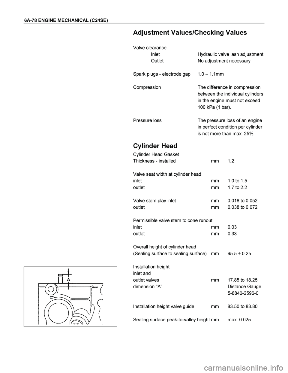
Installation height
inlet and
outlet valves mm 17.85 to 18.25
dimension "A" Distance Gauge
5-8840-2596-0
Installation height valve guide mm 83.50 to 83.80
Sealing surface peak-to-valley height mm max. 0.025
Page 2499 of 4264
 6A-79
Cylinder Head (continued)
Valve System
Valve lifter valve play compensator
(hydraulic)
Valve rotators
(inlet or outlet) outlet
Valve play
(warm or col")
ENGINE MECHANICAL (C24SE) 6A-79
Cylinder Head (continued)
Valve System
Valve lifter valve play compensator
(hydraulic)
Valve rotators
(inlet or outlet) outlet
Valve play
(warm or cold) inlet mm 0
outlet mm 0
Cylinder head height mm 280.3�0.075
Cylinder head bottom, face parallelism mm 0.05
Valve Dimensions
C24SE
A in mm B in
mm C(diameter in mm) and identification mark D
1) 2) Normal K Oversize K1
0.075 Oversize K2
0.150 Oversize A
0.250
Inlet valve 104.2 103.8 41.8 7.012
6.998 7.087
7.073 7.162
7.148 7.262
7.248 44�
Outlet valve 104.0 103.6 36.5 6.992
6.978 7.087
7.053 7.142
7.128 7.242
7.228 44�
Valve stem
bore - 7.050
7.030 7.125
7.105 7.200
7.180 7.300
7.280 -
1) Production
2) Customer service
The P and A department only supplies valves with a length of 103.8mm (inlet valve) and 103.6mm (outlet valve)
only
Camshaft
2.4L
Identification letter K
Colour code Normal size -
0.1mm undersize violet
Radial runout mm 0.03
End play mm 0.09 to 0.21
Cam lift Inlet and outlet valve mm 6.67
 6A-73
Oxygen Sensor (If applicable)
Removal
1. Remove wiring harness plug.
2. Remove oxygen sensor from the front exhaust pipe.
Tighten (Torque)
Oxyg")

RTW46JSH000101
Air Cleaner Filter
NOTE:
The air cleaner filter is not damaged with the edge of the air
cleaner housing.
Removal
(2.4L)")
 6A-75
Spark Plug Thread
Recondition
Ream thread and recut using commercially available spark
plug thread drill (observe manufacturers instructions).")