Page 2484 of 4264

6A-64 ENGINE MECHANICAL (C24SE)
Important!
Do not loosen or open the radiator cap when coolant is hot.
Doing so may cause hot water or steam to splash out, resulting
in burn. When opening the radiator cap, be sure to confirm the
coolant is cold. Cover a thick cloth over the cap and loosen it
slowly to reduce pressure, then open the cap.
6. Close the radiator cap firmly and run the engine at
approx. 2000 rpm. In addition, set the heater temperature
adjuster to the max position to circulate coolant in the
heater conduit system.
7. Confirm that the temperature gauge reads half or more
of full scale and that the thermostat is activated.
Then continue idling 5 minutes more and switch off the
engine, and allow it to cool.
8. After the engine cools down, check the coolant level and
refill it if necessary. When the level is lowered extremely,
check the coolant conduit system and reservoir hose for
leak.
9. Pour coolant into the reservoir to MAX level.
Refill Coolant
Important!
After closing the cooling system, let engine run warm until
thermostat opens (coolant approx. 92�C/197.6F)
Inspection
Coolant level
Allow engine to cool. If necessary, refill coolant.
Check that cooling system self-bleeds during engine warming-
up phase.
Ignition Timing, Check
No Adjustment
Page 2485 of 4264
ENGINE MECHANICAL (C24SE) 6A-65
ENGINE EXTERNAL PARTS
Radiator
Removal
1. Disconnect battery ground cable.
2. Loosen a drain plug to drain EC.
3. Disconnect radiator inlet hose and outlet hose from the engine.
RTW46BSH000101
4. Remove fan guide(1), clips(2) on both sides and the
bottom lock, then remove lower fan guide(3) with fan
shroud(4).
5. Disconnect the reserve tank hose(6) from radiator.
RTW36BMH000101
6. Remove bracket(5).
7. Lift up and remove the radiator assembly with hose,
taking care not to damage the radiator core with a fan
blade.
Page 2486 of 4264
6A-66 ENGINE MECHANICAL (C24SE)
Installation
Follow the removal procedure in the reverse order to install the
radiator.
Thermostat
Removal
1. Remove water outlet nozzles with thermostat from
thermostat housing.
2. Remove coolant hose and collect coolant.
Important!
Remove and Install thermostat only together with water outlet
nozzles.
Tighten (Torque)
Water outlet nozzles to thermostat housing - 8 N�
m (0.8 kgf�
m)
Installation
1. Install coolant hose.
2. Fill cooling system and bleed according to the
corresponding operation.
Water Pump
Removal
1. Remove lower hose band from pipe band and collect
coolant.
2. Remove front toothed belt cover according to the
corresponding operation.
3. Remove water pump from cylinder block after releasing
tension on toothed belt.
Clean
Sealing surfaces
Page 2487 of 4264

ENGINE MECHANICAL (C24SE) 6A-67
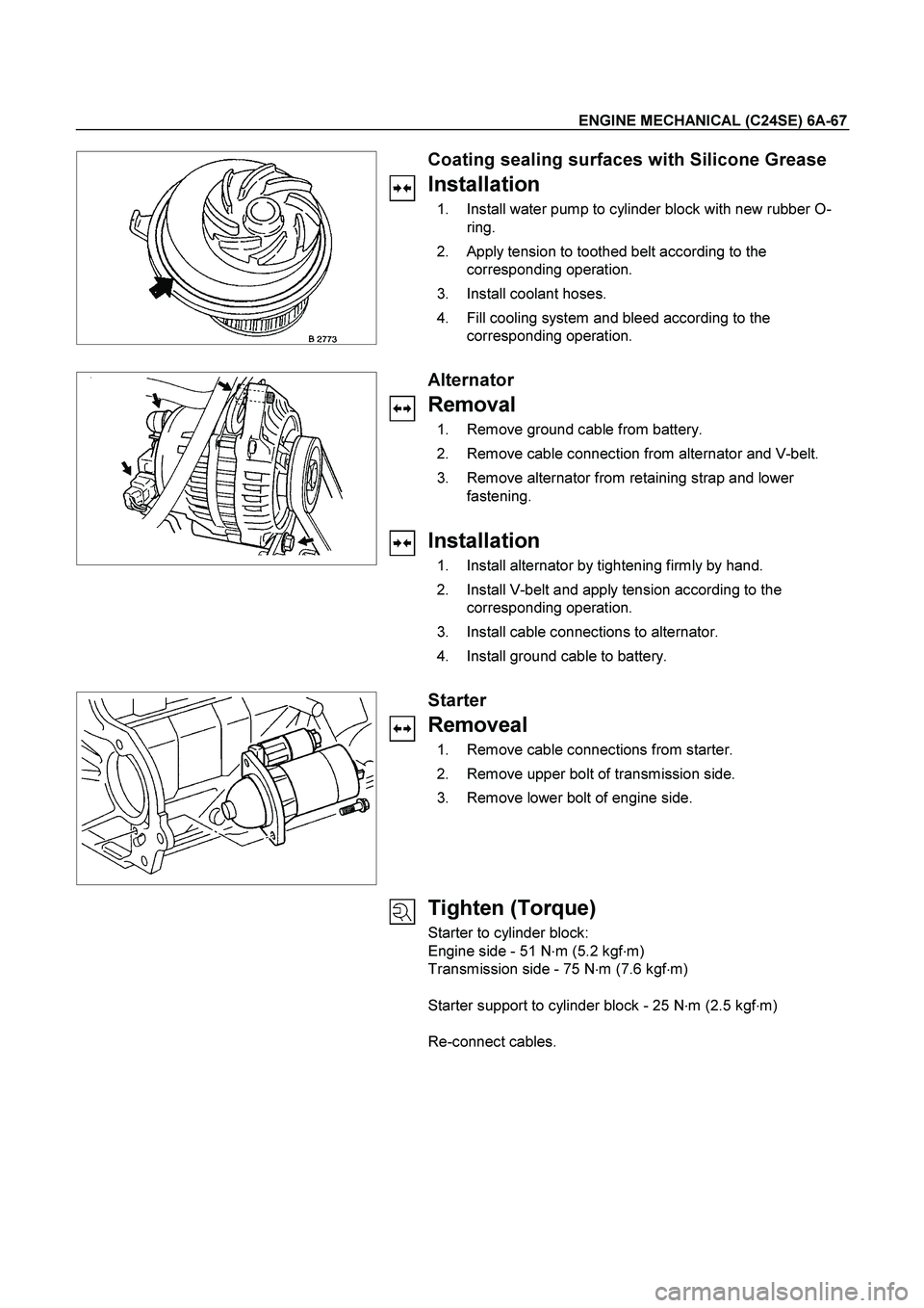
Coating sealing surfaces with Silicone Grease
Installation
1. Install water pump to cylinder block with new rubber O-
ring.
2. Apply tension to toothed belt according to the
corresponding operation.
3. Install coolant hoses.
4. Fill cooling system and bleed according to the
corresponding operation.
Alternator
Removal
1. Remove ground cable from battery.
2. Remove cable connection from alternator and V-belt.
3. Remove alternator from retaining strap and lower
fastening.
Installation
1. Install alternator by tightening firmly by hand.
2. Install V-belt and apply tension according to the
corresponding operation.
3. Install cable connections to alternator.
4. Install ground cable to battery.
Starter
Removeal
1. Remove cable connections from starter.
2. Remove upper bolt of transmission side.
3. Remove lower bolt of engine side.
Tighten (Torque)
Starter to cylinder block:
Engine side - 51 N�
m (5.2 kgf�
m)
Transmission side - 75 N�
m (7.6 kgf�
m)
Starter support to cylinder block - 25 N�
m (2.5 kgf�
m)
Re-connect cables.
Page 2488 of 4264
6A-68 ENGINE MECHANICAL (C24SE)
V-belt Tension of Alternator
Measure
Measure V-belt tension of alternator.
Permitted values for new V-belt are approx. 311-489N (31-50
kgf).
Note:
V-belt to deflection as loaded with 10kg : 8-12mm.
Adjust
Adjust V-belt tension by loosening clamping bracket and lower
alternator bracket and moving alternator.
Tighten (Torque)
Clamping bracket to alternator - 35 N�
m (3.6 kgf�
m)
Lower alternator bracket - 25 N�
m (2.6 kgf�
m)
V-Belt Tension of Power Steering Pump
Measure
Measure V-belt tension of power steering pump. Permitted
values for new belt are approx. 578-712N (59-73 kgf) and 534-
667N (54-68 kgf) for used belt.
Note:
V-belt to deflection as loaded with 10kg : 8-12mm.
Adjust
Adjust V-belt tension by loosening clamping bolt, lower pump
bracket, and adjusting nuts and moving steering pump.
Tighten (Torque)
Adjusting nuts - 18 N�
m (1.8 kgf�
m)
Clamping bolt - 25 N�
m (2.6 kgf�
m)
Lower pump bracket - 26 N�m (2.6 kgf�m)
Page 2489 of 4264
ENGINE MECHANICAL (C24SE) 6A-69
FUEL INJECTION SYSTEM
MAP SENSOR
Removal
1. Disconnect the battery cable.
2. Disconnect the electrical connector from the sensor.
3. Remove the mounting bolts securing the sensor to the manifold.
4. Remove the sensor from the intake manifold.
Installation
1. Push MAP sensor into the manifold.
2. Install the mounting bolts and tighten them.
3. Connect electrical connector.
4. Connect the battery cable.
Pressure Regulator
Removal
1. Remove vacuum hose.
2. Remove fuel hoses.
3. Remove pressure regulator.
Installation
1. Install pressure regulator.
2. Install fuel hoses.
3. Install vacuum hoses.
ECM (Engine Control Module)
Removal
(2.4L)
1. Disconnect the ECM connector.
2. Remove the four hex bolts and nuts.
3. Remove the ECM from the ECM bracket on engine.
Page 2490 of 4264
6A-70 ENGINE MECHANICAL (C24SE)
Installation
(2.4L)
1. Install the ECM to the ECM bracket on engine.
2. Tighten the four screws to the bracket.
3. Connect the connector.
ECT
Removal
1. Remove wiring harness plug and coolant temperature
sensor.
Tighten (Torque)
Temperature sensor to intake pipe - 10 N�
m (1.0 kgf�
m)
Wiring harness plug to temperature sensor
Inspection
Coolant level
Idle Air Control (IAC) Valve
Removal
1. Remove wiring harness plug, hose clamps and idle
speed adjuster.
Installation
1. Install idle speed adjuster, hose clamps and wiring
harness plug.
Ignition Coil
Removal
1. Remove 2 bolts, plug and ignition coil.
Installation
1. Install ignition coil, plug and bolts.
Page 2491 of 4264
ENGINE MECHANICAL (C24SE) 6A-71
Crank Position Sensor
Removal
1. Remove crank position sensor.
Installation
1. Install crank position sensor.