Page 3095 of 4264

pressure
gauge
abnormally
high Reduced or no air flow through
the condenser
��
Condenser clogged o")
HEATER AND AIR CONDITIONING 1-85
RESULT SYMPTOM TROUBLE CAUSE CORRECTION
Discharge
(High)
pressure
gauge
abnormally
high Reduced or no air flow through
the condenser
��
Condenser clogged or dirty
��
Radiator (condenser) fan
does not operate properly ��
Clean
��
Check cooling fan
operation
No bubbles in sight glass when
condenser is cooled by water
(Insufficient cooling)
��Excessive refrigerant in
system
��Check sight glass.
(See “Reading Sight
Glass”)
��
Discharge and
recover refrigerant.
Recharge to specified
amount
After stopping air conditioning,
pressure drops approx. 196 kPa
(2.0kg/cm
2 / 28 PSI) quickly ��
Air in system
��
Evacuate and charge
refrigerant system
Discharge
(High)
pressure
gauge
abnormally
low Insufficient cooling and excessive
bubbles in the sight glass
��
Insufficient refrigerant in
system
��
Check sight glass.
(See “Reading Sight
Glass”)
��Check for leaks
��
Discharge and
recover refrigerant.
Recharge to specified
amount
Low pressure gauge indicates
vacuum ��
Clogged or defective
expansion valve ��
Replace the
expansion valve
Frost or dew on refrigerant line
before and after receiver/ drier or
expansion valve, and low pres-
sure gauge indicates vacuum ��Restriction caused by debris
or moisture in receiver/drier
��Check system for
restriction and
replace receiver/drier
After turning off air conditioning,
high and low pressure gauge
balanced quickly
��
Compressor seal defective
��
Poor compression due to
defective compressor
gasket ��
Replace or repair
compressor
Suction
(Low)
pressure
gauge
abnormally
high Low pressure gauge is lowered
after condenser is cooled by
water
��
Excessive refrigerant in
system
��
Discharge and
recover refrigerant
Recharge to specified
amount
Low pressure hose temperature
around the compressor refrigerant
line connector is lower than
around evaporator
��
Unsatisfactory valve
operation due to defective
temperature sensor of
expansion valve
��
Expansion valve opens too
long ��
Replace the
expansion valve
After turning off air conditioning,
high and low pressure gauge is
balanced quickly ��
Compressor gasket is
defective
��
Replace
Air conditioning turns off before
passenger compartment is
sufficiently
cool ��Electronic thermostat
defective
��Check the electronic
thermostat and
replace as necessary
* For the charging and discharging operations in the table above, refer to “RECOVERY, RECYCLING,
EVACUATION AND CHARGING” in this section.
Page 3096 of 4264

pres-sure
abnormally
low
Condenser is not hot and
excessive bubble in sight glass
��
Insuf")
1-86 HEATER AND AIR CONDITIONING
RESULT SYMPTOM TROUBLE CAUSE CORRECTION
Suction
(Low)
pres-sure
abnormally
low
Condenser is not hot and
excessive bubble in sight glass
��
Insufficient refrigerant
��
Check sight
glass.(See “Reading
Sight Glass”)
��
Check for leaks
��
Discharge and
recover refrigerant.
Recharge to specified
amount
Frost on the expansion valve inlet
line ��
Expansion valve clogged
��
Replace the
expansion valve
A distinct difference in
temperature between the inlet and
outlet refrigerant lines of the
receiver/drier ��
Receiver/drier clogged
��
Replace the receiver/
drier
Expansion valve outlet refrigerant
line is not cold and low-pressure
gauge indicates vacuum
��
The temperature sensor of
the expansion valve is
defective, and the valve
cannot regulate the correct
flow of the refrigerant ��
Replace the
expansion valve
Discharge temperature is low and
air flow from vents is restricted
��Frozen evaporator core fins
��Check electronic
thermostat and
replace as necessary
Low-pressure gauge reading is
low, or a vacuum reading may be
shown ��
Clogged or blocked
refrigerant line
��
Replace refrigerant
line
Suction
(Low) and
Discharge
(High)
pressure
abnor-
mally
high
No bubbles in sight glass after
condenser is cooled by water
(Insufficient cooling)
��
Excessive refrigerant in
system
��
Check sight
glass.(See “Reading
Sight Glass”)
��
Discharge and
recover refrigerant.
Recharge to specified
amount
Reduce air flow through con-
denser
��
Condenser clogged
��Radiator (condenser) fan
does not rotate properly ��
Clean
��Check cooling fan
operation
Suction (Low) pressure hose is
not cold ��
Air in system ��
Evacuate and charge
refrigerant
Suction
(Low) and
Discharge
(High)
pres-sure
abnor-
mally
low
Insufficient cooling and excessive
bubbles in the sight glass ��
Insufficient refrigerant in
system
��
Check sight glass.
(See “Reading Sight
Glass”)
��
Check for leaks
��Discharge and
recover refrigerant.
Recharge to specified
amount
Page 3097 of 4264
HEATER AND AIR CONDITIONING 1-87
MAGNETIC CLUTCH
When the A/C switch and the fan control knob (fan switch) are turned on with the engine running, current flows
through the thermostat and the compressor relay to activate the magnetic clutch.
The air conditioning can be stopped by turning off the A/C switch or the fan control knob (fan switch).
However, even when the air conditioning is in operation, the electronic thermostat, the pressure switch or the ECM
is used to stop the air conditioning temporarily by turning off the magnetic clutch in the prearranged conditions to
reduce the engine load which is being caused by the rise in the engine coolant temperature, and the acceleration of
the vehicle, etc.
Page 3098 of 4264
1-88 HEATER AND AIR CONDITIONING
4JA1 – L
RTW410LF000401
Page 3099 of 4264
HEATER AND AIR CONDITIONING 1-89
4JH1 – TC
RTW410LF000101
Page 3100 of 4264
1-90 HEATER AND AIR CONDITIONING
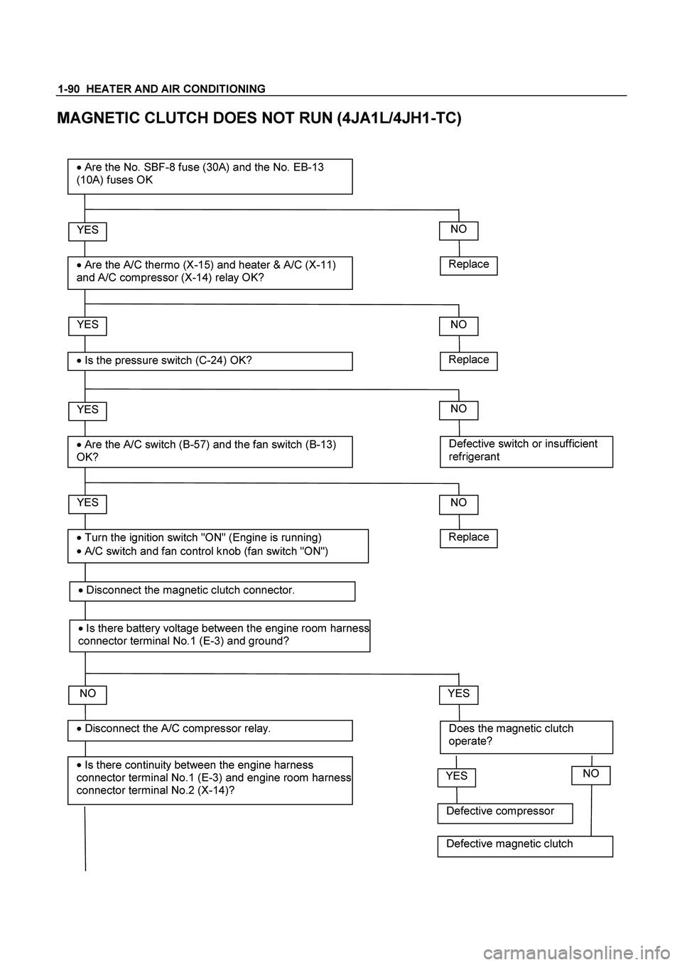
MAGNETIC CLUTCH DOES NOT RUN (4JA1L/4JH1-TC)
Replace
YES
�
Are the A/C thermo (X-15) and heater & A/C (X-11)
and A/C compressor (X-14) relay OK?
� Are the No. SBF-8 fuse (30A) and the No. EB-13
(10A) fuses OK
YES
�
Is the pressure switch (C-24) OK?
YES
�
Are the A/C switch (B-57) and the fan switch (B-13)
OK?
NO
YES
�
Is there continuity between the engine harness
connector terminal No.1 (E-3) and engine room harness
connector terminal No.2 (X-14)?
� Disconnect the A/C compressor relay.
� Turn the ignition switch "ON" (Engine is running)
�
A/C switch and fan control knob (fan switch "ON")
NO
Replace
NO
Defective switch or insufficient
refrigerant
NO
NO
Does the magnetic clutch
operate?
YES
Replace
�
Disconnect the magnetic clutch connector.
� Is there battery voltage between the engine room harness
connector terminal No.1 (E-3) and ground?
Defective compressor
YESNO
Defective magnetic clutch
Page 3101 of 4264

and engine room harness connector
terminal No.2 (X-14).
YES
�
Is there battery v")
HEATER AND AIR CONDITIONING 1-91
Open circuit between the engine
harness connector terminal No.1 (E-3)
and engine room harness connector
terminal No.2 (X-14).
YES
�
Is there battery voltage between the engine room
harness connector terminal No.1 (X-14) and
ground?
YES
�
Disconnect the A/C thermo relay.
YES
�
Is there continuity between the ECM harness
connector terminal No.38 (C-56) and engine
room harness connector terminal No.4 (X-14)?
NO
Open circuit between the No. EB-13
fuse and engine room harness
connector terminal No.1 (X-14).
NO
Open circuit between the engine room
harness connector terminal No.1 (X-
15) and engine room harness
connector terminal No. 3 (X-14).
NO
� Is there continuity between the engine room
harness connector terminal No.3 (X-14) and No.1
(X-15)?
YES
�
Is there continuity between the ECM harness
connector terminal No.30 (C-56) and engine
room harness connector terminal No.2 (X-15)? Open circuit between the engine room
harness connector terminal No.1 (X-
15) and engine room harness
connector terminal No. 3 (X-14).
NO
YES
�
Is there battery voltage between the engine room
harness connector terminal No.4 (X-15) and
ground?
Open circuit between the ECM
harness connector No. 38 (C-56) and
engine room harness connector
terminal No. 4 (X-14).
NO
YES
�
Is there continuity between the engine room
harness connector terminal No. 3 (X-15) and the
engine room harness connector terminal No. 1 (C-
24).
Open circuit between the No. EB-13
fuse and engine room harness
connector terminal No. 4 (X-15).
NO
�
Disconnect the ECM harness connector.
�
Disconnect the pressure switch?
Page 3102 of 4264

1-92 HEATER AND AIR CONDITIONING
YES
� Disconnect the condenser fan relay connector
condenser fan.
YES
�
Is there battery voltage between the engine
room harness connector terminal NO.3 (C-
24) and ground? Open circuit between the condenser
fan relay 4JH1TC No.4 (X-6) 4JA1L
No. 3 (X-13) and engine room harness
connector terminal No. 4 (X-14).
NO
� Is there continuity between the relay terminal
4JH1TC No. 4 (X-6) 4JA1L No.3 (X-13)and
engine room harness connector terminal No.4
(C-24)?
YES
�
connect the A/C thermo relay connector.
Open circuit between the No. EB-13
fuse and engine room harness
connector terminal No. 3 (C-24).
NO
YES
�
Is there battery voltage between the engine
room harness connector terminal No.3 (C-55)
dd?
Open circuit between the engine room
harness connector terminal No. 2 (C-
55) and the engine room harness
connector terminal No. 2 (C-24).
NO
YES
�
Is there continuity between the engine room
harness connector terminal No.1 (C-55) and
ground (C-109) ? or (cooler only) the short
connector terminal No.3 (B-79) and ground (C-
109
)?
Open circuit between the No. EB-13
fuse and engine room harness
connector terminal No. 3 (C-55).
NO
�
Disconnect the electronic themostat.
�
Is there continuity between the engine room
harness connector terminal No. 2 (C-55) and the
engine room harness connector terminal No. 2
(C-24).
Open circuit between and engine room
harness connector terminal No. 3 (X-
15) and the engine room harness
connector terminal No. 1(C-24).
NO
 are turned on with the engine running, current flows
through the thermostat and the comp")