Page 3079 of 4264
HEATER AND AIR CONDITIONING 1-69
REAR HEATER DUCT
REMOVAL AND INSTALLATION
This illustration is based on RHD model
RTW410LF001301
Disassembly Steps
1. Front seat assembly (RH/LH)
� Refer to SECTION 10 “FRONT SEAT”
2. Rear floor console
�
Refer to SECTION 10 “FLOOR
CONSOLE”
3. Front floor console (A/T, M/T Model)
�
Refer to SECTION 10 “FLOOR
CONSOLE”
4. Sill plate (RH/LH)
� Refer to SECTION 10 “INTERIOR
TRIM PANELS”
5. Dash side trim cover (RH/LH)
6. Carpet
7. Clip
8. Rear Heater duct (RH/LH)
9. Rear Heater duct center
Reassembly Steps
9. Rear heater duct center
8. Rear heater duct (RH/LH)
7. Clip
6. Carpet
5. Dash side trim cover (RH/LH)
4. Sill plate (RH/LH)
�
Refer to SECTION 10 “INTERIOR
TRIM PANELS”
3. Front floor console (A/T, M/T Model)
� Refer to SECTION 10 “FLOOR
CONSOLE”
2. Rear floor console
�
Refer to SECTION 10 “FLOOR
CONSOLE”
1. Front seat assembly (RH/LH)
�
Refer to SECTION 10 “FRONT SEAT”
Page 3080 of 4264
1-70 HEATER AND AIR CONDITIONING
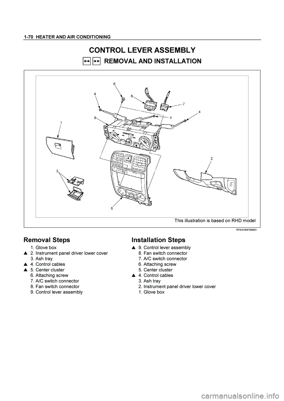
CONTROL LEVER ASSEMBLY
REMOVAL AND INSTALLATION
This illustration is based on RHD model
RTW310MF000601
Removal Steps
1. Glove box
� 2. Instrument panel driver lower cover
3. Ash tray
� 4. Control cables
� 5. Center cluster
6. Attaching screw
7. A/C switch connector
8. Fan switch connector
9. Control lever assembly
Installation Steps
�
9. Control lever assembly
8. Fan switch connector
7. A/C switch connector
6. Attaching screw
5. Center cluster
� 4. Control cables
3. Ash tray
2. Instrument panel driver lower cover
1. Glove box
Page 3081 of 4264
HEATER AND AIR CONDITIONING 1-71
Important Operation - Removal
2. Instrument Panel Driver Lower Cover
Refer to “INSTRUMENT PANEL” in CAB section.
RTW310SH000101
4. Control Cables
Disconnect control cables at each unit side.
5. Center Cluster
Refer to “INSTRUMENT PANEL” in CAB section.
Page 3082 of 4264
 Slide the control lever to the left (“C")
1-72 HEATER AND AIR CONDITIONING
Important Operation - Installation
9. Control Lever Assembly
Air source control cable
RHD
1) Slide the control lever to the left (“CIRC” position).
2) Connect the control cable at the "CIRC" position of the link
unit of blower assembly and fix it with the clip.
LHD
1) Slide the control lever to the right (“FRESH” position).
2) Connect the control cable at the "FRESH" position of the
link unit of blower assembly and fix it with the clip.
Temperature control cable
RHD
1) Turn the control knob to the right (“FULL HOT” position).
2) Connect the control cable at the “FULL HOT” position of the
mix lever of the heater unit and fix it with the clip.
LHD
1) Turn the control knob to the left (“FULL COLD” position).
2) Connect the control cable at the “FULL COLD”position o
f
the mix lever of the heater unit and fix it with the clip.
Air select control cable
RHD
1) Turn the control knob to the left (“VENT” position).
2) Connect the control cable at the “VENT” position of the
mode control link of the heater unit and fix it with the clip.
LHD
1) Turn the control knob to the right (“DEF” position).
2) Connect the control cable at the “DEF” position of the mode
control link of the heater unit and fix it with the clip.
4. Control Cables
Check control cable operation
Page 3083 of 4264
HEATER AND AIR CONDITIONING 1-73
RTW410MF000201
Page 3084 of 4264
1-74 HEATER AND AIR CONDITIONING
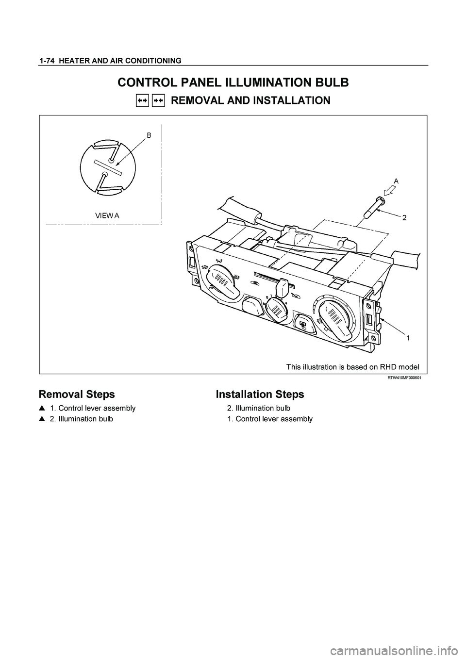
CONTROL PANEL ILLUMINATION BULB
REMOVAL AND INSTALLATION
This illustration is based on RHD model
RTW410MF000601
Removal Steps
� 1. Control lever assembly
� 2. Illumination bulb
Installation Steps
2. Illumination bulb
1. Control lever assembly
Page 3085 of 4264
HEATER AND AIR CONDITIONING 1-75
Important Operation - Removal
1. Control lever assembly
Refer to “CONTROL LEVER ASSEMBLY” in this section.
2. Illumination Bulb
To remove the illumination bulb, insert an ordinary screwdriver
into the slot (B) at the back of the bulb. Turn the bulb
counterclockwise and pull it free.
Page 3086 of 4264
1-76 HEATER AND AIR CONDITIONING
INSPECTION AND REPAIR
840R300005-X
Resistor
As for air-conditioning model, fixed on left (RHD) / right (LHD)
side of the evaporator unit.
As for heater only model, fixed on left (RHD) / right (LHD) side
of the duct placed between blower unit and heater unit.
Replace the resistor with a new on if the coil is found to be
open or if the resistance value deviates from the specified
range.
Terminal Resistance
3 – 2 1.99 �
3 – 4 0.9 �
3 – 1 0.17 �
Blower motor
Check blower motor for smooth rotation.
Connect the battery positive terminal to the No.1 terminal of the
blower motor and negative to the No.2.
Be sure to check to see if the blower motor operates correctly.
")


 / right (LHD)
side of the evaporator unit.
As for he")