Page 3063 of 4264
HEATER AND AIR CONDITIONING 1-53
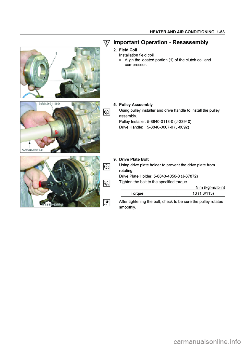
Important Operation - Resassembly
2. Field Coil
Installation field coil.
�
Align the located portion (1) of the clutch coil and
compressor.
5. Pulley Asssembly
Using pulley installer and drive handle to install the pulley
assembly.
Pulley Installer: 5-8840-0118-0 (J-33940)
Drive Handle: 5-8840-0007-0 (J-8092)
9. Drive Plate Bolt
Using drive plate holder to prevent the drive plate from
rotating.
Drive Plate Holder: 5-8840-4056-0 (J-37872)
Tighten the bolt to the specified torque.
N�m (kgf�m/Ib�in)
Torque 13 (1.3/113)
After tightening the bolt, check to be sure the pulley rotates
smoothly.
Page 3064 of 4264
1-54 HEATER AND AIR CONDITIONING
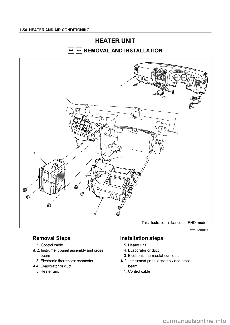
HEATER UNIT
REMOVAL AND INSTALLATION
This illustration is based on RHD model
RTW310LF000501-X
Removal Steps
1. Control cable
� 2. Instrument panel assembly and cross
beam
3. Electronic thermostat connector
� 4. Evaporator or duct
5. Heater unit
Installation steps
5. Heater unit
4. Evaporator or duct
3. Electronic thermostat connector
� 2. Instrument panel assembly and cross
beam
1. Control cable
Page 3065 of 4264
HEATER AND AIR CONDITIONING 1-55
Important Operations – Removal
2. Instrument Panel Assembly and Cross Beam.
Refer to INSTRUMENT PANEL in CAB section.
4. Evaporator or Duct
Refer to “EVAPORATOR” or “DUCT” in this section.
Important Operation - Installation
2. Instrument Panel Assembly and Cross Beam
Adjust the heater control cables.
Refer to "CONTROL LEVER ASSEMBLY" in this section.
Page 3066 of 4264

1-56 HEATER AND AIR CONDITIONING
DISASSEMBLY AND REASSEMBLY
This illustration is based on RHD model
RTW310LF001401
Disassembly Steps
1. Attaching screw
2. Main link-side
3. Sub link-side
4. Mode rod
5. Holder rod
6. Mode lever
7. DEF/FOOT-spring
8. VENT-spring
9. Heater box clip
10. Attaching screws
11. Foot duct
12. Fod H/Pipes seal
13. Heater core clamp
14. Heater core
15. Mix lever (2)
16. Mix lever (1)
17. Control cable clamp
18. Attaching screws
19. Upper case
20. Lower case
21. DEF/FOOT door
22. VENT door
23. Mix door
24. Control cable clamp
Reassembly Steps
24. Control cable clamp
23. Mix door
22. VENT door
21. DEF/FOOT door
20. Lower case
19. Upper case
18 Attaching screws
17. Control cable clamp
16. Mix lever (1)
15. Mix lever (2)
14. Heater core
13. Heater core clamp
12. Fod H/Pipes seal
11. Foot duct
10. Attaching screws
9. Heater box clip
8. VENT-spring
7. DEF/FOOT-spring
6. Mode lever
5. Holder rod
4. Mode rod
3. Sub link-side
2. Main link-side
1. Attaching screw
Page 3067 of 4264
HEATER AND AIR CONDITIONING 1-57
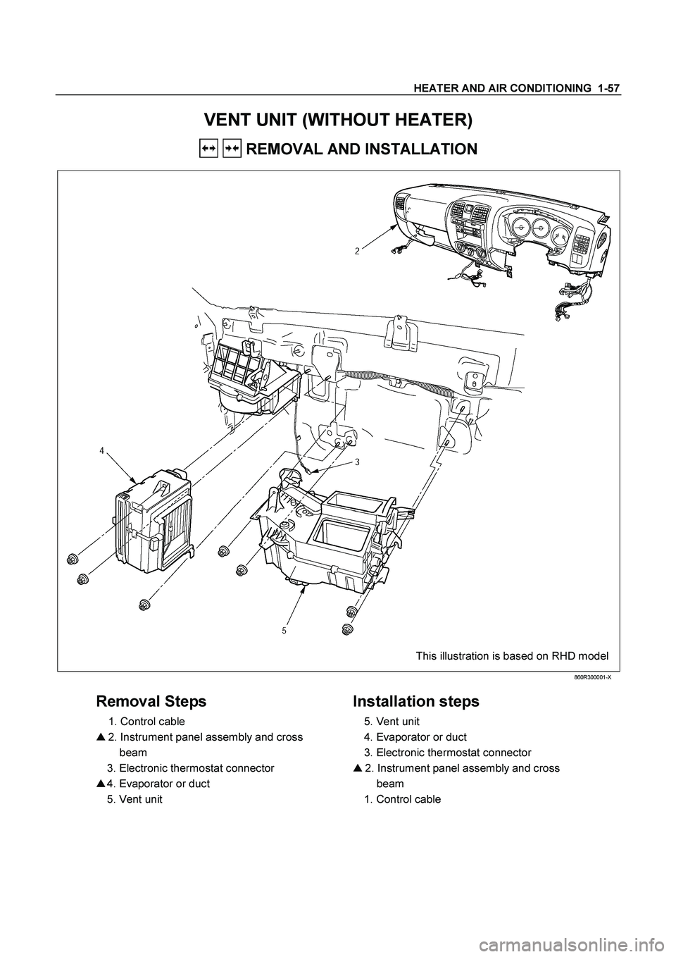
VENT UNIT (WITHOUT HEATER)
REMOVAL AND INSTALLATION
This illustration is based on RHD model
860R300001-X
Removal Steps
1. Control cable
� 2. Instrument panel assembly and cross
beam
3. Electronic thermostat connector
� 4. Evaporator or duct
5. Vent unit
Installation steps
5. Vent unit
4. Evaporator or duct
3. Electronic thermostat connector
� 2. Instrument panel assembly and cross
beam
1. Control cable
Page 3068 of 4264
1-58 HEATER AND AIR CONDITIONING
Important Operations - Removal
2. Instrument Panel Assembly and Cross Beam.
Refer to INSTRUMENT PANEL in CAB section.
4. Evaporator or Duct
Refer to “EVAPORATOR” or “DUCT” in this section.
Important Operation - Installation
2. Instrument Panel Assembly and Cross Beam
Adjust the heater control cables.
Refer to "CONTROL LEVER ASSEMBLY" in this section.
Page 3069 of 4264
HEATER AND AIR CONDITIONING 1-59
DISASSEMBLY AND REASSEMBLY
This illustration is based on RHD model
Disassembly Steps
1. Attaching screw
2. Main link-side
3. Sub link-side
4. Mode rod
5. Holder rod
6. Mode lever
7. DEF/FOOT-spring
8. VENT-spring
9. FOD H/pipes seal
10. Heater box clip
11. Attaching screws
12. Foot duct
13. Heater core clamp
14. Upper case
15. Lower case
16. DEF/FOOT door
17. VENT door
18. Control cable clamp
Reassembly Steps
18. Control cable clamp
17. VENT door
16. DEF/FOOT door
15. Lower case
14. Upper case
13. Heater core clamp
12. Foot duct
11. Attaching screws
10. Heater box clip
9. FOD H/pipes seal
8. VENT-spring
7. DEF/FOOT-spring
6. Mode lever
5. Holder rod
4. Mode rod
3. Sub link-side
2. Main link-side
1. Attaching screw
Page 3070 of 4264
1-60 HEATER AND AIR CONDITIONING
EVAPORATOR (WITH A/C)
REMOVAL AND INSTALLATION
This illustration is based on RHD model
Removal Steps
1. Glove box
2. Passenger lower bracket
3. Electronic thermostat connector
4. Drain hose
5. Refrigerant line
6. Evaporator assembly
Installation Steps
6. Evaporator assembly
5. Refrigerant line
4. Drain hose
3. Electronic thermostat connector
2. Passenger lower bracket
1. Glove box


REMOVAL AND INSTALLATION
This illustration is based on RHD model
Removal Steps
1. Glove box
2. Passenger lower bracket")