Page 3055 of 4264
HEATER AND AIR CONDITIONING 1-45
Important Operations - Installation
4. Bolt; Compressor to Bracket
N�m (kgf�m/lb�ft)
Torque 19 (1.9/14)
3. Refrigerant Line
N�m (kgf�m/lb�ft)
Torque 11�19 (1.1/9.5�1.9/14)
2. Compressor Belt
Move compressor belt tensioner to loose side using
wrench, then install serpentine belt to normal position.
Page 3056 of 4264
1-46 HEATER AND AIR CONDITIONING
GENERAL REPAIR PROCEDURE
OIL SPECIFICATION
�
The HFC-134a system requires a synthetic (PAG)
compressor oil.
�
Compressor (PAG) oil varies according to compressor
model. Be sure to use oil specified for the model of
compressor.
Specified Compressor Oil
DH-PR
HANDLING OF OIL
�
The oil should be free from moisture, dust, metal powder,
etc.
� Do not mix with other oil.
� The water content in the oil increases when exposed to the
air. After use, seal oil from air immediately.
�
The compressor oil must be stored in steel containers, not
in plastic containers.
COMPRESSOR OIL CHECK
The Oil used to lubricate the compressor is circulating with the
refrigerant.
Whenever replacing any component of the system or a large
amount of gas leakage occurs, add oil to maintain the original
amount of. oil.
Oil Capacity
Capacity total in
system CR-14 180 cm3 (5.0 fl.oz.)
Compressor
(Service parts)
charging amount
CR-14
180 cm
3 (5.0 fl.oz.)
Page 3057 of 4264
 Perform Oil return operation.
(Refer to \"Oil Return Operation\" in this section.)
(2) Discharge refrigerant and")
HEATER AND AIR CONDITIONING 1-47
Checking and Adjusting for Used Compressor
(1) Perform Oil return operation.
(Refer to "Oil Return Operation" in this section.)
(2) Discharge refrigerant and remove the compressor.
(3) Drain the compressor oil and measure the extracted oil with
a measuring cylinder.
(4) Check the compressor oil for contamination.
(Refer to "Contamination of Compressor Oil" in this
section.)
(5) Adjust oil level following the procedure below.
Type Collected Amount Charging Amount
more than 90 cm3
(3.0 fl.oz.) same as collected
amount
less than 90 cm3
(3.0 fl.oz.) 90 cm3 (3.0 fl.oz.) CR-14
(6) Install the compressor, then evacuate, charge and perform
oil return operation.
(7) Check system operation.
When it is impossible to perform oil return operation, the
compressor oil should be checked in the following order:
(1) Discharge refrigerant and remove the compressor.
(2) Drain the compressor oil and measure the extracted oil with
a measuring cylinder.
(3) Check the oil for contamination.
(4) If more than 90 cm
3 (3.0 fl.oz.) for CR-14 type is extracted
from the compressor, supply same amount of oil to the
compressor to be installed.
If the amount of oil extracted is less than 90 cm
3 (3.0 fl.oz.)
for CR-14 type recheck the compressor oil in the following
order:
(5) Supply 90 cm
3 (3.0 fl.oz.) for CR-14 type oil to the
compressor and install it onto the vehicle.
(6) Perform oil return operation.
(7) Remove the compressor and recheck the amount of oil.
(8) Adjust the compressor oil.
Page 3058 of 4264
 of oil is charged in compressor (service
parts). So it is necessary to drain the prop")
1-48 HEATER AND AIR CONDITIONING
Checking and Adjusting for Compressor
Replacement
180 cm3 (5.0 lmp fl oz) of oil is charged in compressor (service
parts). So it is necessary to drain the proper amount of oil from
the new compressor.
1) Perform oil return operation.
2) Discharge refrigerant and remove the compressor.
3) Drain the compressor oil and measure the extracted oil.
4) Check the compressor oil for contamination.
5) Adjust oil level as required.
Amount of oil drained
From used compressor Draining amount of oil
From new compressor
less than
90 cm
3 (2.5 lmp fl oz) Some as drained
amount
more than
90 cm
3 (2.5 lmp fl oz) 90 cm
3 (2.5 lmp fl oz)
6) Evacuate, charge and perform oil return operation.
7) Check system operation.
CONTAMINATION OF COMPRESSOR OIL
Unlike engine oil, no cleaning agent is added to the
compressor oil. Even is the compressor runs for a long period
of time (approximately 1 season), the oil never becomes
contaminated as long as there is nothing wrong with the
compressor or its method of use.
Inspect the extracted oil for any of the following
conditions:
� The capacity of the oil has increased.
� The oil has changed color to red.
�
Foreign substances, metal powder, etc., are present in the
oil.
If any of these conditions exists, compressor oil is
contaminated. Whenever contaminated compressor oil is
discovered, the receiver/drier must be replaced.
Page 3059 of 4264

HEATER AND AIR CONDITIONING 1-49
OIL RETURN OPERATION
There is close affinity between the oil and the refrigerant.
During normal operation, part of the oil recirculates with the
refrigerant in the system.
When checking the amount of oil in the system, or replacing
any component of the system, the compressor must be run in
advance for oil return operation. The procedure is as follows:
1) Open the all doors and engine hood.
2) Start the engine and A/C switch is "ON" and Set the fan
control knob at its highest position.
3) Run the compressor for more than 20 minutes between
800 and 1,000 rpm in order to operate the system.
4) Stop the engine.
REPLACEMENT OF COMPONENT PARTS
When replacing system component parts, supply the following
amount of oil to the component parts to be installed.
Component parts to be installed Amount of oil
Evaporator 50 cm3 (1.7 fl.oz.)
Condenser 30 cm3 (1.0 fl.oz.)
Receiver/drier 30 cm3 (1.0 fl.oz.)
Refrigerant line (One piece) 10 cm3 (0.3 fl.oz.)
Refrigeration oil must be replenished if more than two parts
are removed at the same time. After installing these
components, check compressor oil.
Page 3060 of 4264
1-50 HEATER AND AIR CONDITIONING
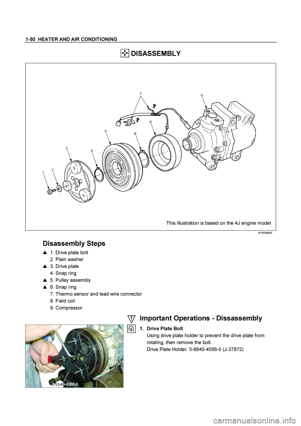
DISASSEMBLY
This illustration is based on the 4J engine model
871R300002
Disassembly Steps
� 1. Drive plate bolt
2. Plain washer
� 3. Drive plate
4. Snap ring
� 5. Pulley assembly
� 6. Snap ring
7. Thermo sensor and lead wire connector
8. Field coil
9. Compressor
Important Operations - Dissassembly
1. Drive Plate Bolt
Using drive plate holder to prevent the drive plate from rotating, then remove the bolt.
Drive Plate Holder: 5-8840-4056-0 (J-37872)
Page 3061 of 4264
HEATER AND AIR CONDITIONING 1-51
3. Drive Plate
Remove the drive plate.
If the frictional surface shows signs of damage due to
excessive heat, the drive plate and pulley should be
replaced.
5. Pulley Assembly
Using pulley puller pilot and pulley puller to remove the
pulley assembly.
Pulley Puller Pilot: 5-8840-0121-0 (J-33943)
Pulley Puller: 5-8840-0111-0 (J-8433)
Check the appearance of the pulley assembly. If the
frictional surface of the pulley shows signs of excessive
grooving due to slippage, both the pulley and drive plate
should be replaced. The frictional surfaces of the pulley
assembly should be cleaned with a suitable solvent before
reinstallation.
6. Snap ring
Using snap ring pliers to remove the snap ring.
Page 3062 of 4264
1-52 HEATER AND AIR CONDITIONING
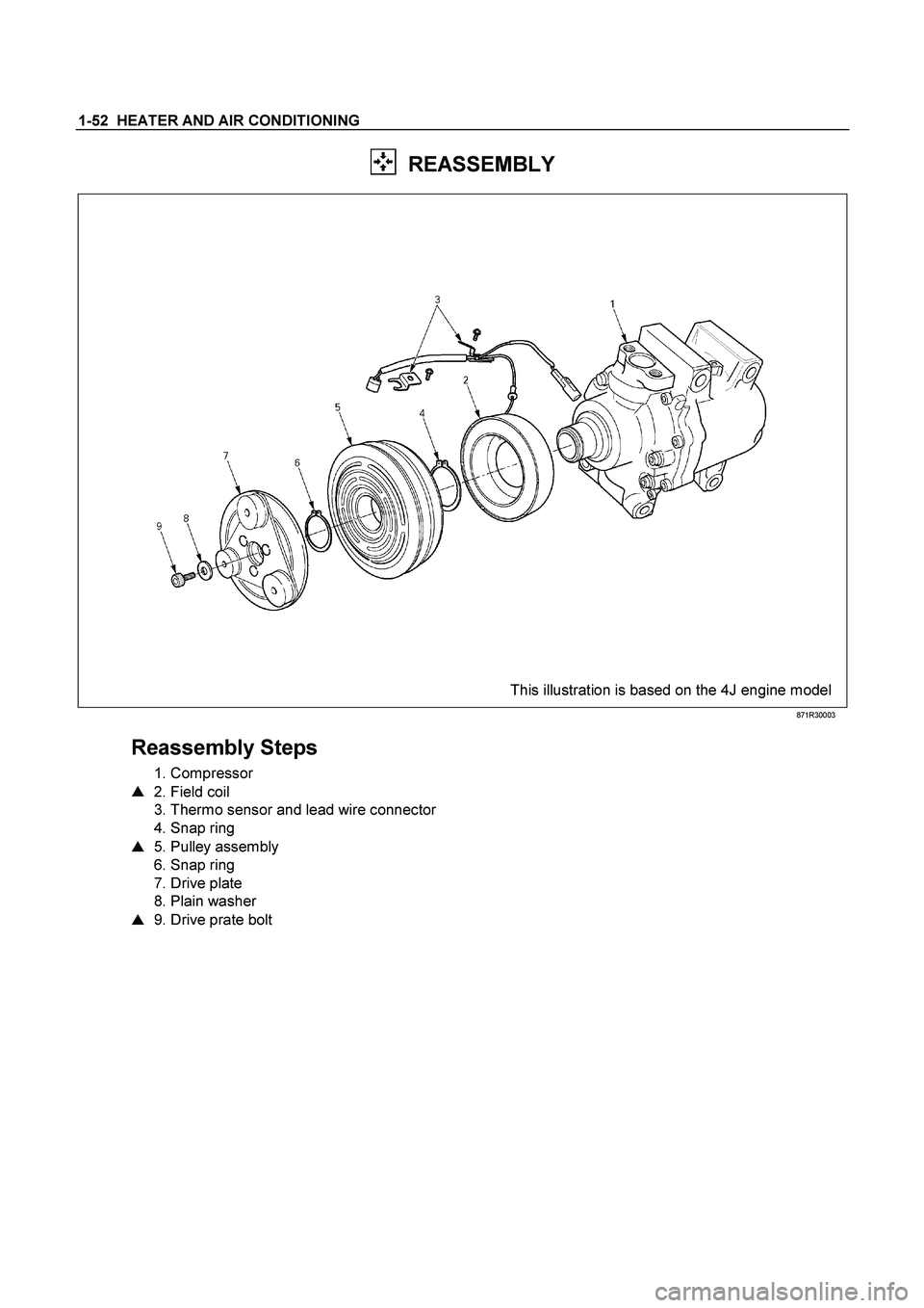
REASSEMBLY
This illustration is based on the 4J engine model
871R30003
Reassembly Steps
1. Compressor
� 2. Field coil
3. Thermo sensor and lead wire connector
4. Snap ring
� 5. Pulley assembly
6. Snap ring
7. Drive plate
8. Plain washer
� 9. Drive prate bolt