Page 3084 of 4264
1-74 HEATER AND AIR CONDITIONING
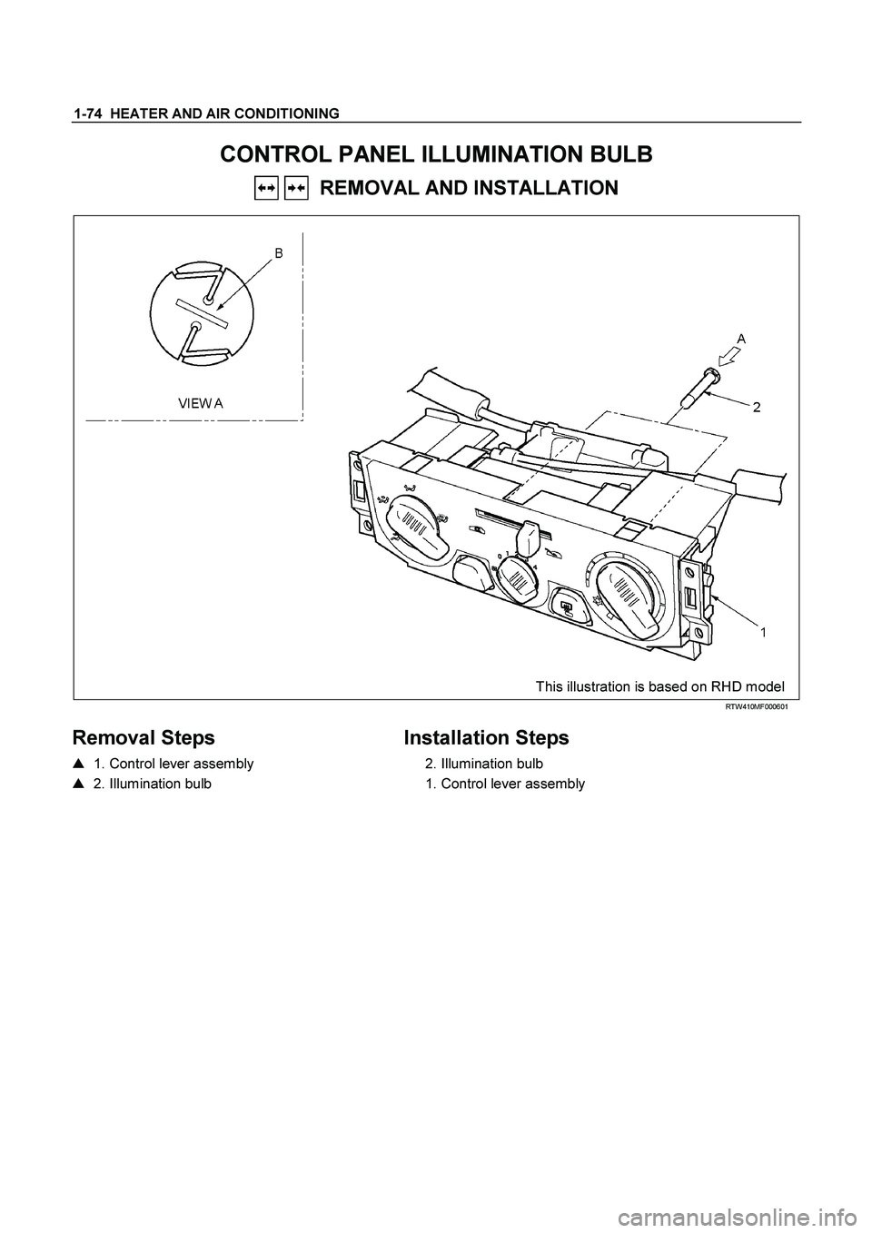
CONTROL PANEL ILLUMINATION BULB
REMOVAL AND INSTALLATION
This illustration is based on RHD model
RTW410MF000601
Removal Steps
� 1. Control lever assembly
� 2. Illumination bulb
Installation Steps
2. Illumination bulb
1. Control lever assembly
Page 3085 of 4264
HEATER AND AIR CONDITIONING 1-75
Important Operation - Removal
1. Control lever assembly
Refer to “CONTROL LEVER ASSEMBLY” in this section.
2. Illumination Bulb
To remove the illumination bulb, insert an ordinary screwdriver
into the slot (B) at the back of the bulb. Turn the bulb
counterclockwise and pull it free.
Page 3086 of 4264
1-76 HEATER AND AIR CONDITIONING
INSPECTION AND REPAIR
840R300005-X
Resistor
As for air-conditioning model, fixed on left (RHD) / right (LHD)
side of the evaporator unit.
As for heater only model, fixed on left (RHD) / right (LHD) side
of the duct placed between blower unit and heater unit.
Replace the resistor with a new on if the coil is found to be
open or if the resistance value deviates from the specified
range.
Terminal Resistance
3 – 2 1.99 �
3 – 4 0.9 �
3 – 1 0.17 �
Blower motor
Check blower motor for smooth rotation.
Connect the battery positive terminal to the No.1 terminal of the
blower motor and negative to the No.2.
Be sure to check to see if the blower motor operates correctly.
Page 3087 of 4264
HEATER AND AIR CONDITIONING 1-77
D08R300070
Fan switch and Circuit board
Check for continuity between fan switch and A/C switch side
connector terminals.
B-13 B-57
Terminal
No.
SW.
position
1 2 3 4 5 6 2 3 10 11
OFF
1
2
3
(FAN SW.)
4
OFF CIRCUIT
BOARD
(A/C SW.)
ON
Electronic Thermostat
Check for continuity between electronic thermostat side
connector terminals.
(Cooler)
RTW410SH000201
(A/C)
Page 3088 of 4264
1-78 HEATER AND AIR CONDITIONING
RTW4A0SH000201
Pressure switch
Disconnect pressure switch connector and check for continuity
between pressure switch side connector terminal.
825r300045
Heater and thermo switch relay.
Check for continuity between the relay terminals.
1 - 5 �����
No continuity
(When battery voltage is applied between 2 - 4 )
1 - 5 �����
Continuity
825r300023
Check for continuity between the relay terminals.
1 - 2 �����
No continuity
(When battery voltage is applied between 3 - 4 )
1 - 2 �����
Continuity
Page 3089 of 4264
HEATER AND AIR CONDITIONING 1-79
TROUBLESHOOTING
FAN CONTROL KNOB (FAN SWITCH)
Current flows to the blower motor through the Heater & A/C relay (X-11) to activate the rotation of the blower motor
by turning “ON” the fan control knob (fan switch). Blower motor speed is controlled in stages by the resistor, by
operating the switch from “LOW” to “HIGH.”
D08R300046-X2
Page 3090 of 4264
1-80 HEATER AND AIR CONDITIONING
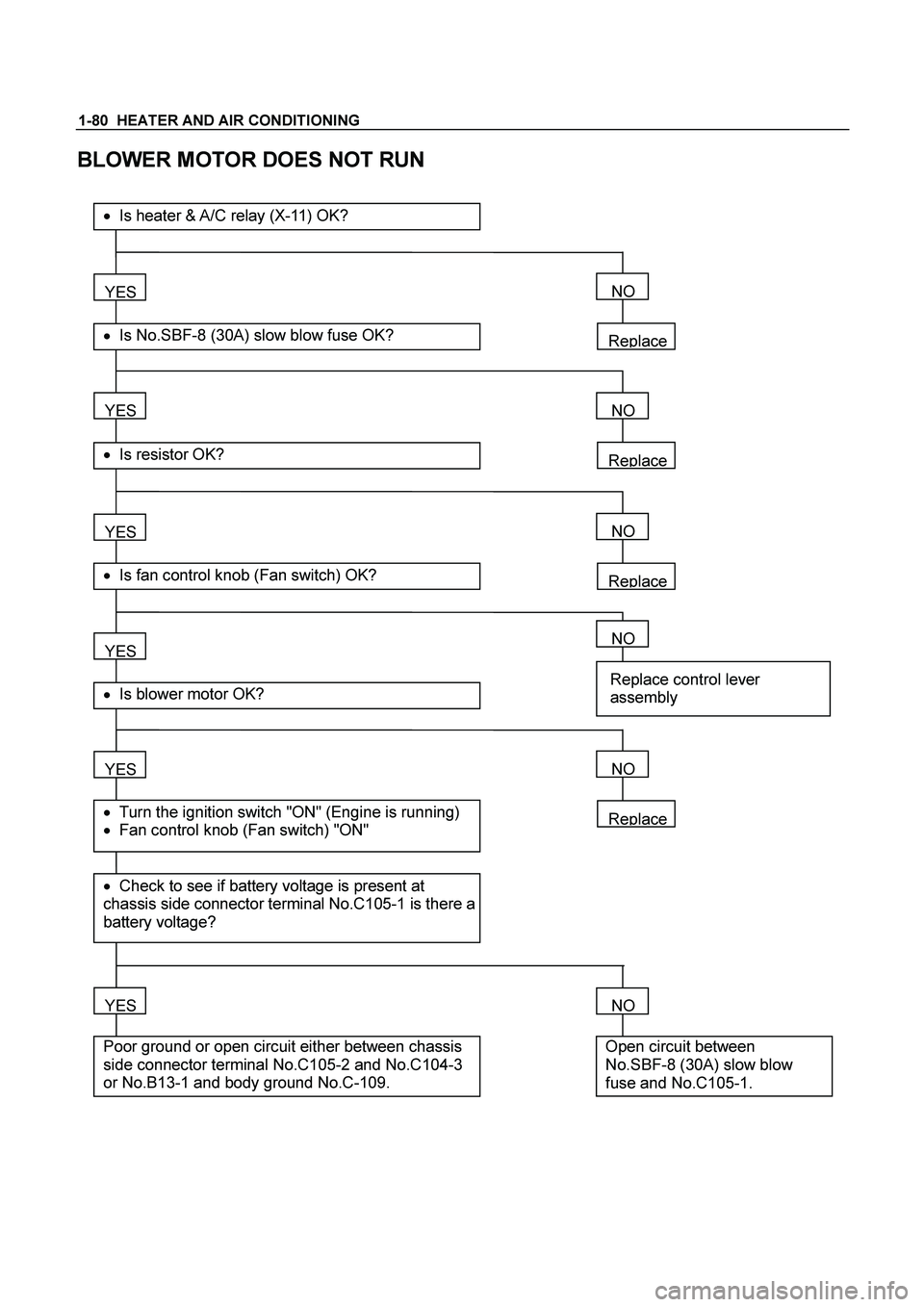
BLOWER MOTOR DOES NOT RUN
Replace
YES
� Is No.SBF-8 (30A) slow blow fuse OK?
��Is heater & A/C relay (X-11) OK?
YES
� Is resistor OK?
YES
� Is fan control knob (Fan switch) OK?
YES
YES
� Check to see if battery voltage is present at
chassis side connector terminal No.C105-1 is there a
battery voltage?
� Turn the ignition switch "ON" (Engine is running)
� Fan control knob (Fan switch) "ON"
� Is blower motor OK?
YES
Poor ground or open circuit either between chassis
side connector terminal No.C105-2 and No.C104-3
or No.B13-1 and body ground No.C-109.
NO
Replace
NO
Replace
NO
NO
Replace control lever
assembly
Replace
NO
NO
Open circuit between
No.SBF-8 (30A) slow blow
fuse and No.C105-1.
Page 3091 of 4264
HEATER AND AIR CONDITIONING 1-81
BLOWER MOTOR DOES NOT RUN IN CERTAIN POSITION
A 1: (Low)
Blower motor does no
tB 2: (Medium Low) Position
run at
C 3: (Medium Hi)
D 4: (High)
* Checkin
g is performed only when in the malfunction
mode.
�
Is resist or OK?
YES
�
Is fan control knob (Fan switch) OK?
YES
Condition:
�
O
pen circuit between chassis side connector
terminal No. C104-2 and No. B13-3
B Condition :
�
O
pen circuit between chassis side connector
terminal No. C104-4 and No. B13-6
C Condition:
�
O
pen circuit between chassis side connector
terminal No. C104-1 and No. B13-5
D Condition:
�
O
pen circuit between chassis side connector
terminal No. C105-2 a nd No. B13-4
Replace
NO
NO
Replace control leverassembly A

 / right (LHD)
side of the evaporator unit.
As for he")


Current flows to the blower motor through the Heater & A/C relay (X-11) to activate the rotation of the blower motor")

Blower motor does no
tB 2: (Medium Low) Position
run at
C 3: (Medium Hi)
D 4: (High)
* Checkin")