Page 3068 of 4264
1-58 HEATER AND AIR CONDITIONING
Important Operations - Removal
2. Instrument Panel Assembly and Cross Beam.
Refer to INSTRUMENT PANEL in CAB section.
4. Evaporator or Duct
Refer to “EVAPORATOR” or “DUCT” in this section.
Important Operation - Installation
2. Instrument Panel Assembly and Cross Beam
Adjust the heater control cables.
Refer to "CONTROL LEVER ASSEMBLY" in this section.
Page 3069 of 4264
HEATER AND AIR CONDITIONING 1-59
DISASSEMBLY AND REASSEMBLY
This illustration is based on RHD model
Disassembly Steps
1. Attaching screw
2. Main link-side
3. Sub link-side
4. Mode rod
5. Holder rod
6. Mode lever
7. DEF/FOOT-spring
8. VENT-spring
9. FOD H/pipes seal
10. Heater box clip
11. Attaching screws
12. Foot duct
13. Heater core clamp
14. Upper case
15. Lower case
16. DEF/FOOT door
17. VENT door
18. Control cable clamp
Reassembly Steps
18. Control cable clamp
17. VENT door
16. DEF/FOOT door
15. Lower case
14. Upper case
13. Heater core clamp
12. Foot duct
11. Attaching screws
10. Heater box clip
9. FOD H/pipes seal
8. VENT-spring
7. DEF/FOOT-spring
6. Mode lever
5. Holder rod
4. Mode rod
3. Sub link-side
2. Main link-side
1. Attaching screw
Page 3070 of 4264
1-60 HEATER AND AIR CONDITIONING
EVAPORATOR (WITH A/C)
REMOVAL AND INSTALLATION
This illustration is based on RHD model
Removal Steps
1. Glove box
2. Passenger lower bracket
3. Electronic thermostat connector
4. Drain hose
5. Refrigerant line
6. Evaporator assembly
Installation Steps
6. Evaporator assembly
5. Refrigerant line
4. Drain hose
3. Electronic thermostat connector
2. Passenger lower bracket
1. Glove box
Page 3071 of 4264
HEATER AND AIR CONDITIONING 1-61
DISASSEMBLY AND REASSEMBLY
This illustration is based on RHD model
RTW410MF000501
Disassembly Steps
1. Packing cooler outlet
2. Packing cooler inlet
3. Seal fod cooler
4. Filter cover assembly
5. Air filter
6. Electronic thermostat
7. Clip heater
8. Attaching screws
9. Case : cooler upper
10. Case : cooler lower
11. Insulator : case lower
12. Drain hose
13. Packing drain
14. Evaporator assembly W/Expansion valve
15. Grommet : A/C pipe
Reassembly Steps
15. Grommet : A/C pipe
14. Evaporator assembly W/Expansion valve
13. Packing drain
12. Drain hose
11. Insulator : case lower
10. Case : cooler lower
9. Case : cooler upper
8. Attaching screws
7. Clip heater
� 6. Electronic thermostat
5. Air filter
4. Filter cover assembly
3. Seal fod cooler
2. Packing cooler inlet
1. Packing cooler outlet
Page 3072 of 4264
1-62 HEATER AND AIR CONDITIONING
This illustration is based on RHD model
Important Operation -Reassembly
6. Electronic Thermostat
1) Install the electronic thermostat to the evaporator core
specified position with the clip.
2) Sensor part must not interfere with the evaporator core.
Page 3073 of 4264
HEATER AND AIR CONDITIONING 1-63
DUCT (WITHOUT A/C)
REMOVAL AND INSTALLATION
This illustration is based on RHD model
RTW310LF001601
Removal Steps
1. Glove box
2. Passenger lower bracket
3. Evaporator assembly
Installation Steps
3. Evaporator assembly
2. Passenger lower bracket
1. Glove box
Page 3074 of 4264
1-64 HEATER AND AIR CONDITIONING
DISASSEMBLY AND REASSEMBLY
This illustration is based on RHD model
RTW310LF001501
Disassembly Steps
1. Packing cooler outlet
2. Packing cooler inlet
3. Seal fod cooler
4. Filter cover assembly
5. Clip heater
6. Attaching screws
7. Case : cooler upper
8. Case : cooler lower
9. Packing drain
10. Grommet : A/C pipe
Reassembly Steps
10. Grommet
9. Packing drain
8. Case : cooler lower
7. Case : cooler upper
6. Attaching screws
5. Clip heater
4. Filter cover assembly
3. Seal fod cooler
2. Packing cooler inlet
1. Packing cooler outlet
Page 3075 of 4264
HEATER AND AIR CONDITIONING 1-65
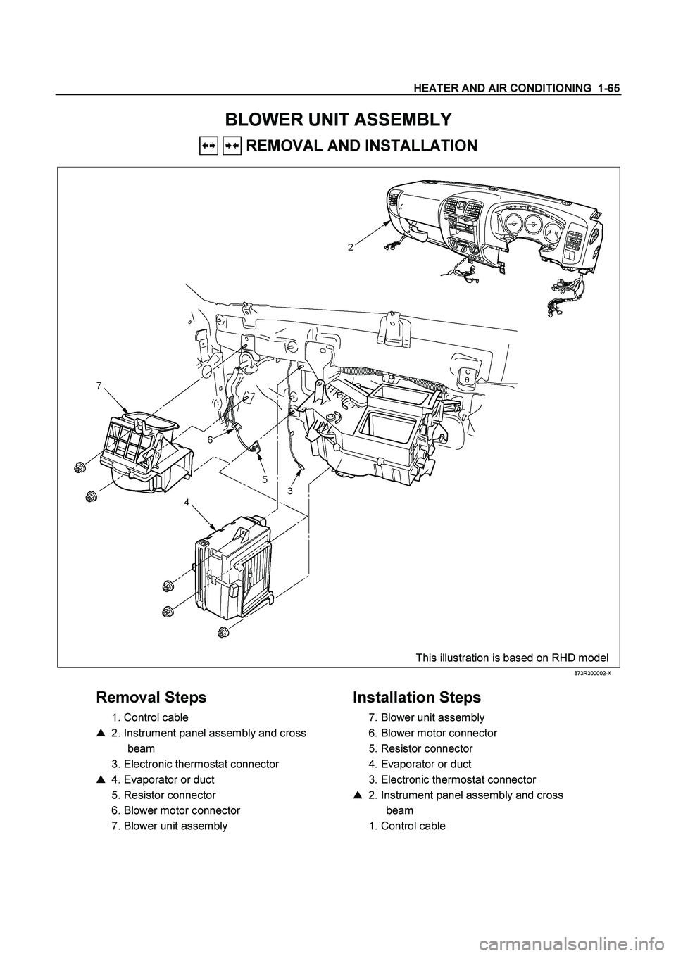
BLOWER UNIT ASSEMBLY
REMOVAL AND INSTALLATION
This illustration is based on RHD model
873R300002-X
Removal Steps
1. Control cable
� 2. Instrument panel assembly and cross
beam
3. Electronic thermostat connector
� 4. Evaporator or duct
5. Resistor connector
6. Blower motor connector
7. Blower unit assembly
Installation Steps
7. Blower unit assembly
6. Blower motor connector
5. Resistor connector
4. Evaporator or duct
3. Electronic thermostat connector
� 2. Instrument panel assembly and cross
beam
1. Control cable


REMOVAL AND INSTALLATION
This illustration is based on RHD model
Removal Steps
1. Glove box
2. Passenger lower bracket")

 Install the electronic thermostat to the evaporator core
sp")

REMOVAL AND INSTALLATION
This illustration is based on RHD model
RTW310LF001601
Removal Steps
1. Glove box
2. Passenger lowe")