Page 3076 of 4264
1-66 HEATER AND AIR CONDITIONING
Important Operation - Installation
2. Instrument Panel Assembly and Cross Beam
Refer to “INSTRUMENT PANEL” in CAB section.
4. Evaporator or Duct
Refer to “EVAPORATOR” or “DUCT” in this section.
Important Operation - Installation
2. Instrument Panel Assembly and Cross Beam
Adjust the heater control cables.
Refer to “CONTOROL LEVER ASSEMBLY” in this section.
Page 3077 of 4264
HEATER AND AIR CONDITIONING 1-67
DISASSEMBLY AND REASSEMBLY
This illustration is based on RHD model
Disassembly Steps
1. Attaching screw
2. Intake link
3. Intake lever
4. Intake packing
5. Attaching screws
6. Blower motor assembly
7. Attaching screw
8. Flat resistor
9. Upper case
10. Lower case
11. Mode door
12. Bell mouth
13. Control cable clamp
Reassembly Steps
13. Control cable clamp
12. Bell mouth
11. Mode door
10. Lower case
9. Upper case
8. Flat resistor
7. Attaching screw
6. Blower motor assembly
5. Attaching screws
4. Intake packing
3. Intake lever
2. Intake link
1. Attaching screw
Page 3078 of 4264
1-68 HEATER AND AIR CONDITIONING
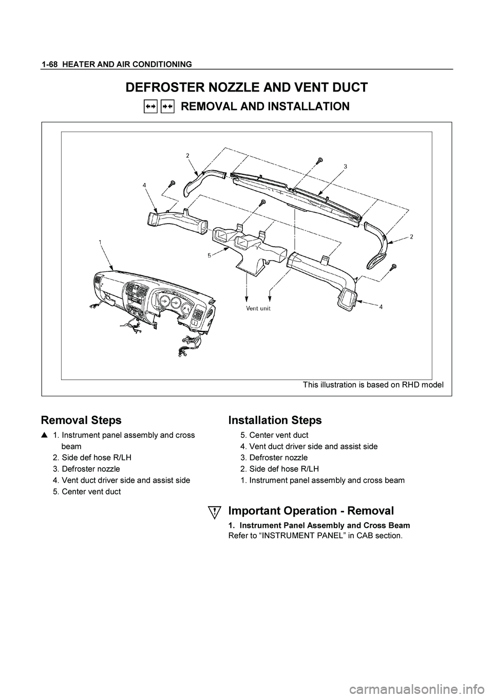
DEFROSTER NOZZLE AND VENT DUCT
REMOVAL AND INSTALLATION
This illustration is based on RHD model
Removal Steps
� 1. Instrument panel assembly and cross
beam
2. Side def hose R/LH
3. Defroster nozzle
4. Vent duct driver side and assist side
5. Center vent duct
Installation Steps
5. Center vent duct
4. Vent duct driver side and assist side
3. Defroster nozzle
2. Side def hose R/LH
1. Instrument panel assembly and cross beam
Important Operation - Removal
1. Instrument Panel Assembly and Cross Beam
Refer to “INSTRUMENT PANEL ” in CAB section.
Page 3079 of 4264
HEATER AND AIR CONDITIONING 1-69
REAR HEATER DUCT
REMOVAL AND INSTALLATION
This illustration is based on RHD model
RTW410LF001301
Disassembly Steps
1. Front seat assembly (RH/LH)
� Refer to SECTION 10 “FRONT SEAT”
2. Rear floor console
�
Refer to SECTION 10 “FLOOR
CONSOLE”
3. Front floor console (A/T, M/T Model)
�
Refer to SECTION 10 “FLOOR
CONSOLE”
4. Sill plate (RH/LH)
� Refer to SECTION 10 “INTERIOR
TRIM PANELS”
5. Dash side trim cover (RH/LH)
6. Carpet
7. Clip
8. Rear Heater duct (RH/LH)
9. Rear Heater duct center
Reassembly Steps
9. Rear heater duct center
8. Rear heater duct (RH/LH)
7. Clip
6. Carpet
5. Dash side trim cover (RH/LH)
4. Sill plate (RH/LH)
�
Refer to SECTION 10 “INTERIOR
TRIM PANELS”
3. Front floor console (A/T, M/T Model)
� Refer to SECTION 10 “FLOOR
CONSOLE”
2. Rear floor console
�
Refer to SECTION 10 “FLOOR
CONSOLE”
1. Front seat assembly (RH/LH)
�
Refer to SECTION 10 “FRONT SEAT”
Page 3080 of 4264
1-70 HEATER AND AIR CONDITIONING
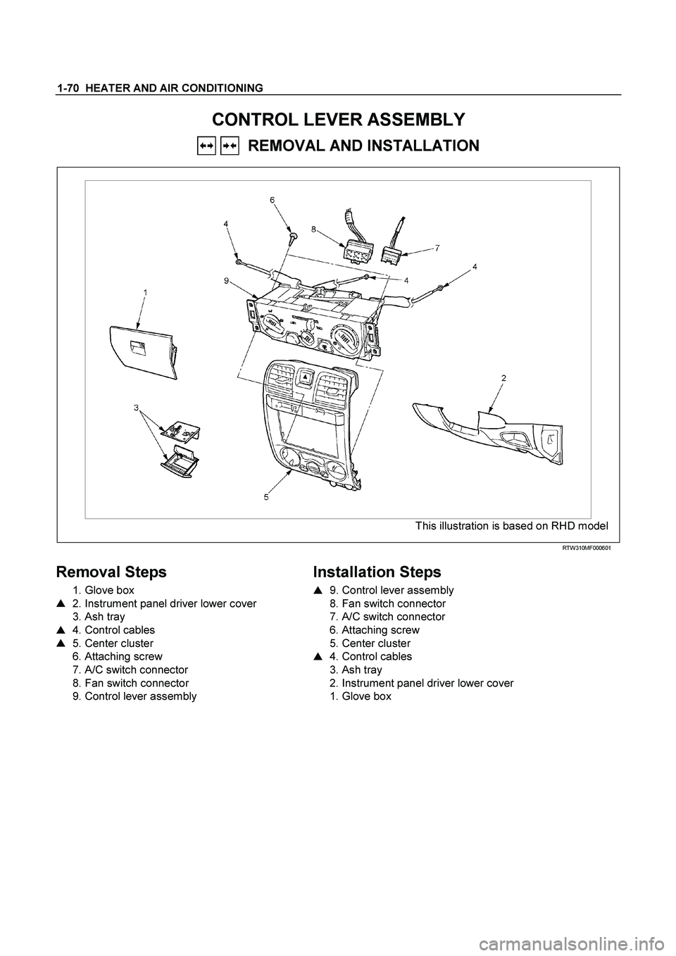
CONTROL LEVER ASSEMBLY
REMOVAL AND INSTALLATION
This illustration is based on RHD model
RTW310MF000601
Removal Steps
1. Glove box
� 2. Instrument panel driver lower cover
3. Ash tray
� 4. Control cables
� 5. Center cluster
6. Attaching screw
7. A/C switch connector
8. Fan switch connector
9. Control lever assembly
Installation Steps
�
9. Control lever assembly
8. Fan switch connector
7. A/C switch connector
6. Attaching screw
5. Center cluster
� 4. Control cables
3. Ash tray
2. Instrument panel driver lower cover
1. Glove box
Page 3081 of 4264
HEATER AND AIR CONDITIONING 1-71
Important Operation - Removal
2. Instrument Panel Driver Lower Cover
Refer to “INSTRUMENT PANEL” in CAB section.
RTW310SH000101
4. Control Cables
Disconnect control cables at each unit side.
5. Center Cluster
Refer to “INSTRUMENT PANEL” in CAB section.
Page 3082 of 4264
 Slide the control lever to the left (“C")
1-72 HEATER AND AIR CONDITIONING
Important Operation - Installation
9. Control Lever Assembly
Air source control cable
RHD
1) Slide the control lever to the left (“CIRC” position).
2) Connect the control cable at the "CIRC" position of the link
unit of blower assembly and fix it with the clip.
LHD
1) Slide the control lever to the right (“FRESH” position).
2) Connect the control cable at the "FRESH" position of the
link unit of blower assembly and fix it with the clip.
Temperature control cable
RHD
1) Turn the control knob to the right (“FULL HOT” position).
2) Connect the control cable at the “FULL HOT” position of the
mix lever of the heater unit and fix it with the clip.
LHD
1) Turn the control knob to the left (“FULL COLD” position).
2) Connect the control cable at the “FULL COLD”position o
f
the mix lever of the heater unit and fix it with the clip.
Air select control cable
RHD
1) Turn the control knob to the left (“VENT” position).
2) Connect the control cable at the “VENT” position of the
mode control link of the heater unit and fix it with the clip.
LHD
1) Turn the control knob to the right (“DEF” position).
2) Connect the control cable at the “DEF” position of the mode
control link of the heater unit and fix it with the clip.
4. Control Cables
Check control cable operation
Page 3083 of 4264
HEATER AND AIR CONDITIONING 1-73
RTW410MF000201


")