Page 3060 of 4264
1-50 HEATER AND AIR CONDITIONING
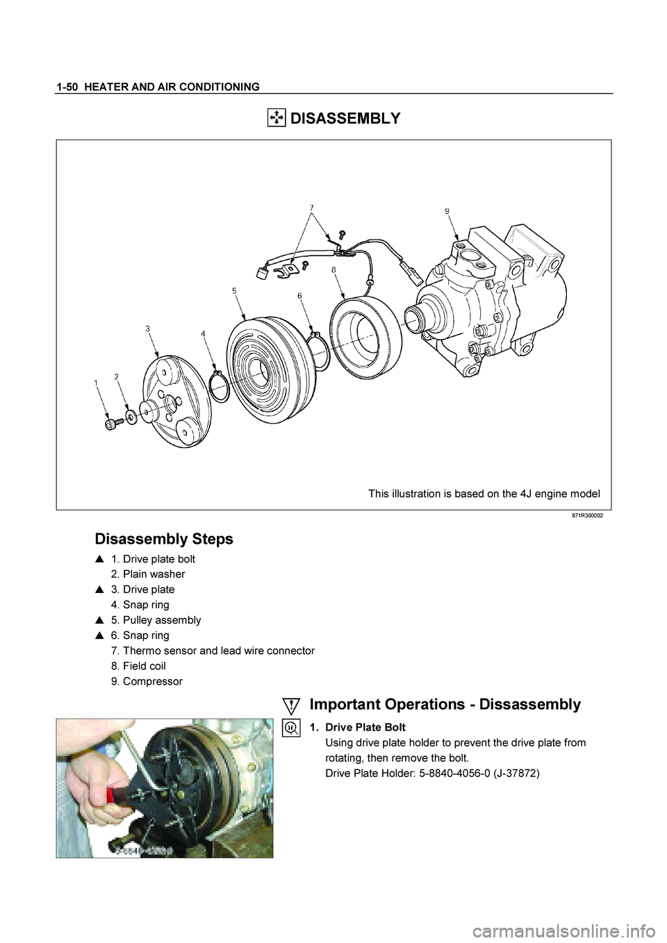
DISASSEMBLY
This illustration is based on the 4J engine model
871R300002
Disassembly Steps
� 1. Drive plate bolt
2. Plain washer
� 3. Drive plate
4. Snap ring
� 5. Pulley assembly
� 6. Snap ring
7. Thermo sensor and lead wire connector
8. Field coil
9. Compressor
Important Operations - Dissassembly
1. Drive Plate Bolt
Using drive plate holder to prevent the drive plate from rotating, then remove the bolt.
Drive Plate Holder: 5-8840-4056-0 (J-37872)
Page 3061 of 4264
HEATER AND AIR CONDITIONING 1-51
3. Drive Plate
Remove the drive plate.
If the frictional surface shows signs of damage due to
excessive heat, the drive plate and pulley should be
replaced.
5. Pulley Assembly
Using pulley puller pilot and pulley puller to remove the
pulley assembly.
Pulley Puller Pilot: 5-8840-0121-0 (J-33943)
Pulley Puller: 5-8840-0111-0 (J-8433)
Check the appearance of the pulley assembly. If the
frictional surface of the pulley shows signs of excessive
grooving due to slippage, both the pulley and drive plate
should be replaced. The frictional surfaces of the pulley
assembly should be cleaned with a suitable solvent before
reinstallation.
6. Snap ring
Using snap ring pliers to remove the snap ring.
Page 3062 of 4264
1-52 HEATER AND AIR CONDITIONING
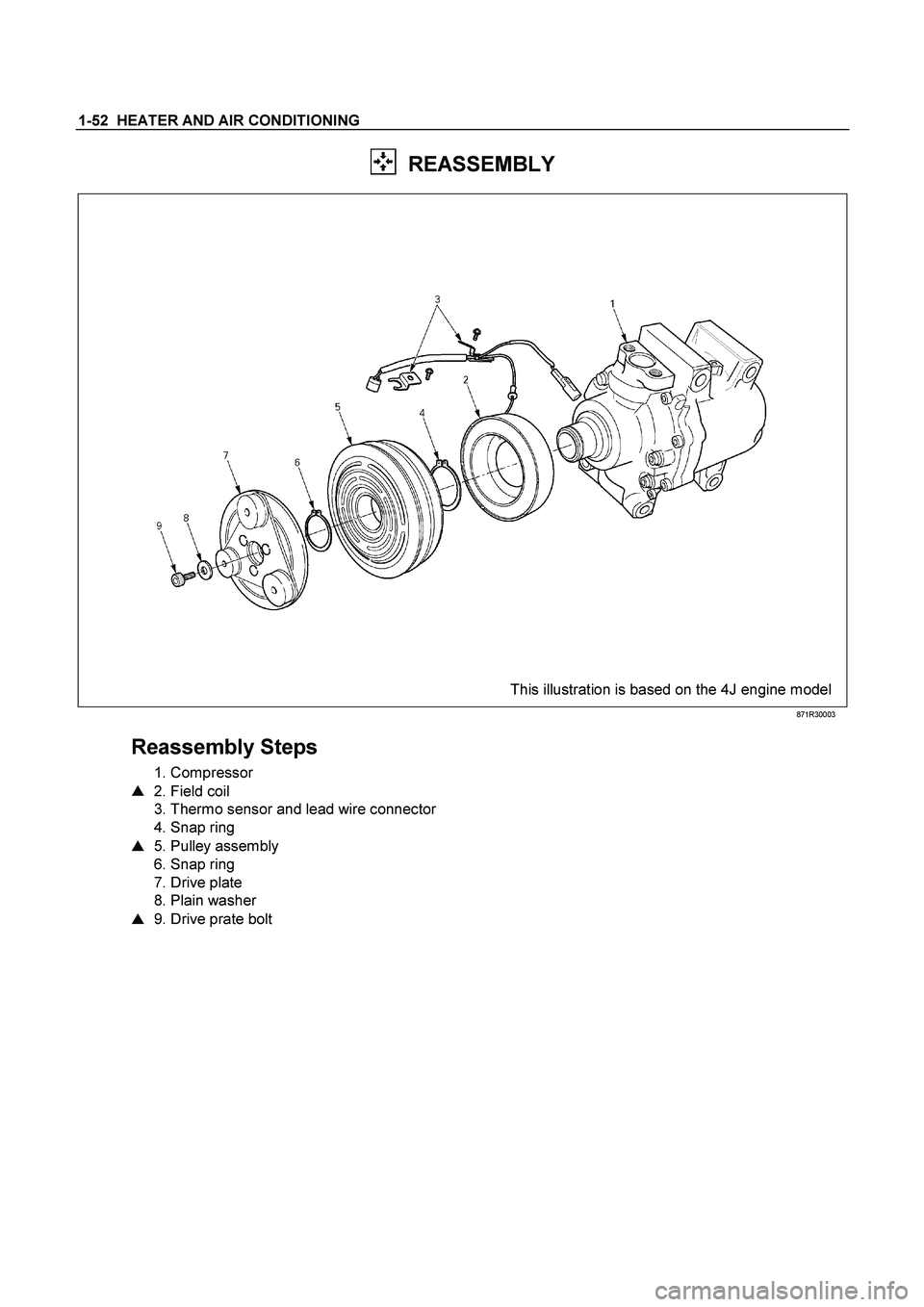
REASSEMBLY
This illustration is based on the 4J engine model
871R30003
Reassembly Steps
1. Compressor
� 2. Field coil
3. Thermo sensor and lead wire connector
4. Snap ring
� 5. Pulley assembly
6. Snap ring
7. Drive plate
8. Plain washer
� 9. Drive prate bolt
Page 3063 of 4264
HEATER AND AIR CONDITIONING 1-53
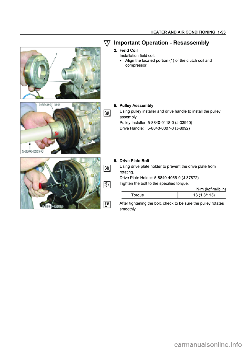
Important Operation - Resassembly
2. Field Coil
Installation field coil.
�
Align the located portion (1) of the clutch coil and
compressor.
5. Pulley Asssembly
Using pulley installer and drive handle to install the pulley
assembly.
Pulley Installer: 5-8840-0118-0 (J-33940)
Drive Handle: 5-8840-0007-0 (J-8092)
9. Drive Plate Bolt
Using drive plate holder to prevent the drive plate from
rotating.
Drive Plate Holder: 5-8840-4056-0 (J-37872)
Tighten the bolt to the specified torque.
N�m (kgf�m/Ib�in)
Torque 13 (1.3/113)
After tightening the bolt, check to be sure the pulley rotates
smoothly.
Page 3064 of 4264
1-54 HEATER AND AIR CONDITIONING
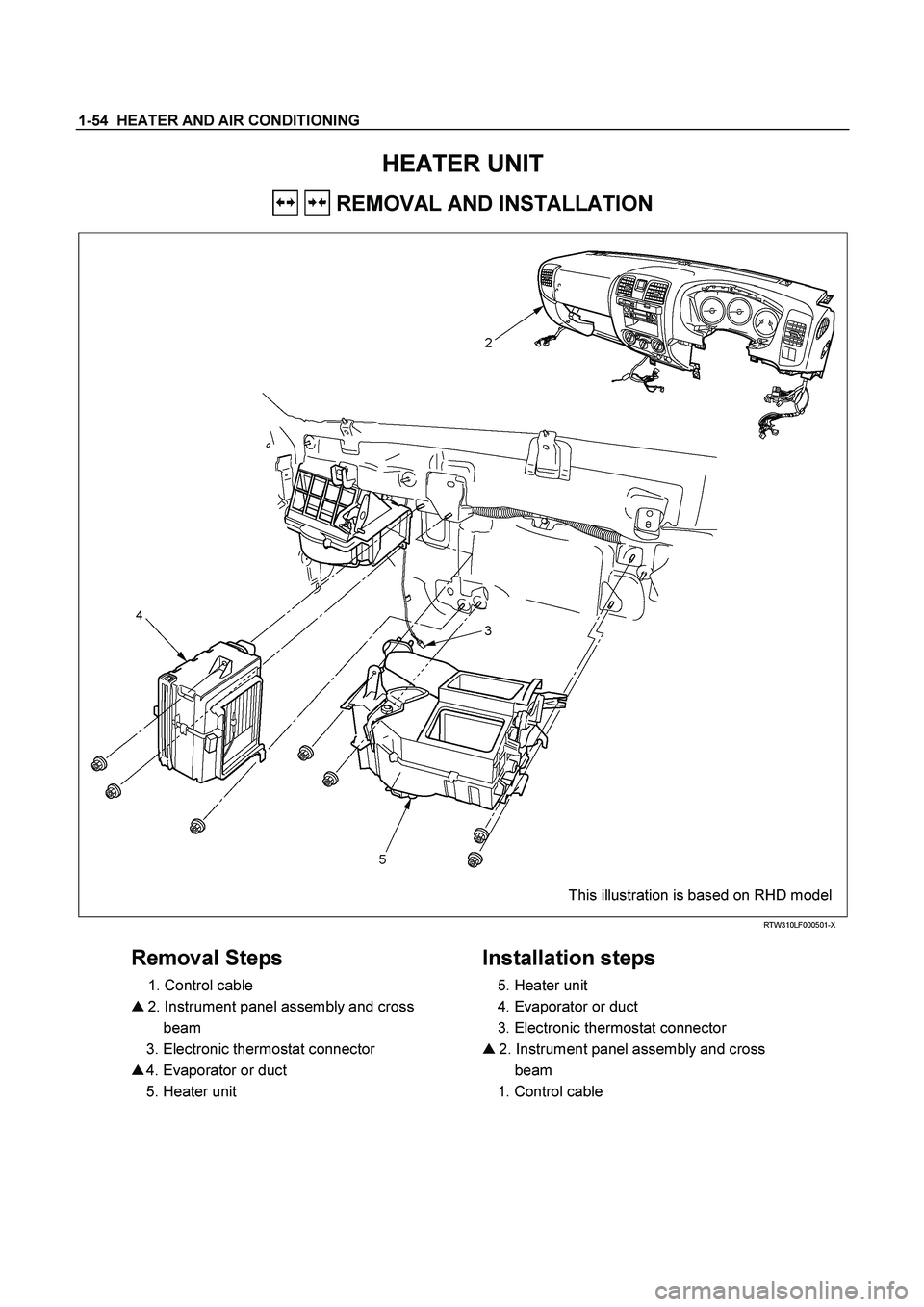
HEATER UNIT
REMOVAL AND INSTALLATION
This illustration is based on RHD model
RTW310LF000501-X
Removal Steps
1. Control cable
� 2. Instrument panel assembly and cross
beam
3. Electronic thermostat connector
� 4. Evaporator or duct
5. Heater unit
Installation steps
5. Heater unit
4. Evaporator or duct
3. Electronic thermostat connector
� 2. Instrument panel assembly and cross
beam
1. Control cable
Page 3065 of 4264
HEATER AND AIR CONDITIONING 1-55
Important Operations – Removal
2. Instrument Panel Assembly and Cross Beam.
Refer to INSTRUMENT PANEL in CAB section.
4. Evaporator or Duct
Refer to “EVAPORATOR” or “DUCT” in this section.
Important Operation - Installation
2. Instrument Panel Assembly and Cross Beam
Adjust the heater control cables.
Refer to "CONTROL LEVER ASSEMBLY" in this section.
Page 3066 of 4264

1-56 HEATER AND AIR CONDITIONING
DISASSEMBLY AND REASSEMBLY
This illustration is based on RHD model
RTW310LF001401
Disassembly Steps
1. Attaching screw
2. Main link-side
3. Sub link-side
4. Mode rod
5. Holder rod
6. Mode lever
7. DEF/FOOT-spring
8. VENT-spring
9. Heater box clip
10. Attaching screws
11. Foot duct
12. Fod H/Pipes seal
13. Heater core clamp
14. Heater core
15. Mix lever (2)
16. Mix lever (1)
17. Control cable clamp
18. Attaching screws
19. Upper case
20. Lower case
21. DEF/FOOT door
22. VENT door
23. Mix door
24. Control cable clamp
Reassembly Steps
24. Control cable clamp
23. Mix door
22. VENT door
21. DEF/FOOT door
20. Lower case
19. Upper case
18 Attaching screws
17. Control cable clamp
16. Mix lever (1)
15. Mix lever (2)
14. Heater core
13. Heater core clamp
12. Fod H/Pipes seal
11. Foot duct
10. Attaching screws
9. Heater box clip
8. VENT-spring
7. DEF/FOOT-spring
6. Mode lever
5. Holder rod
4. Mode rod
3. Sub link-side
2. Main link-side
1. Attaching screw
Page 3067 of 4264
HEATER AND AIR CONDITIONING 1-57
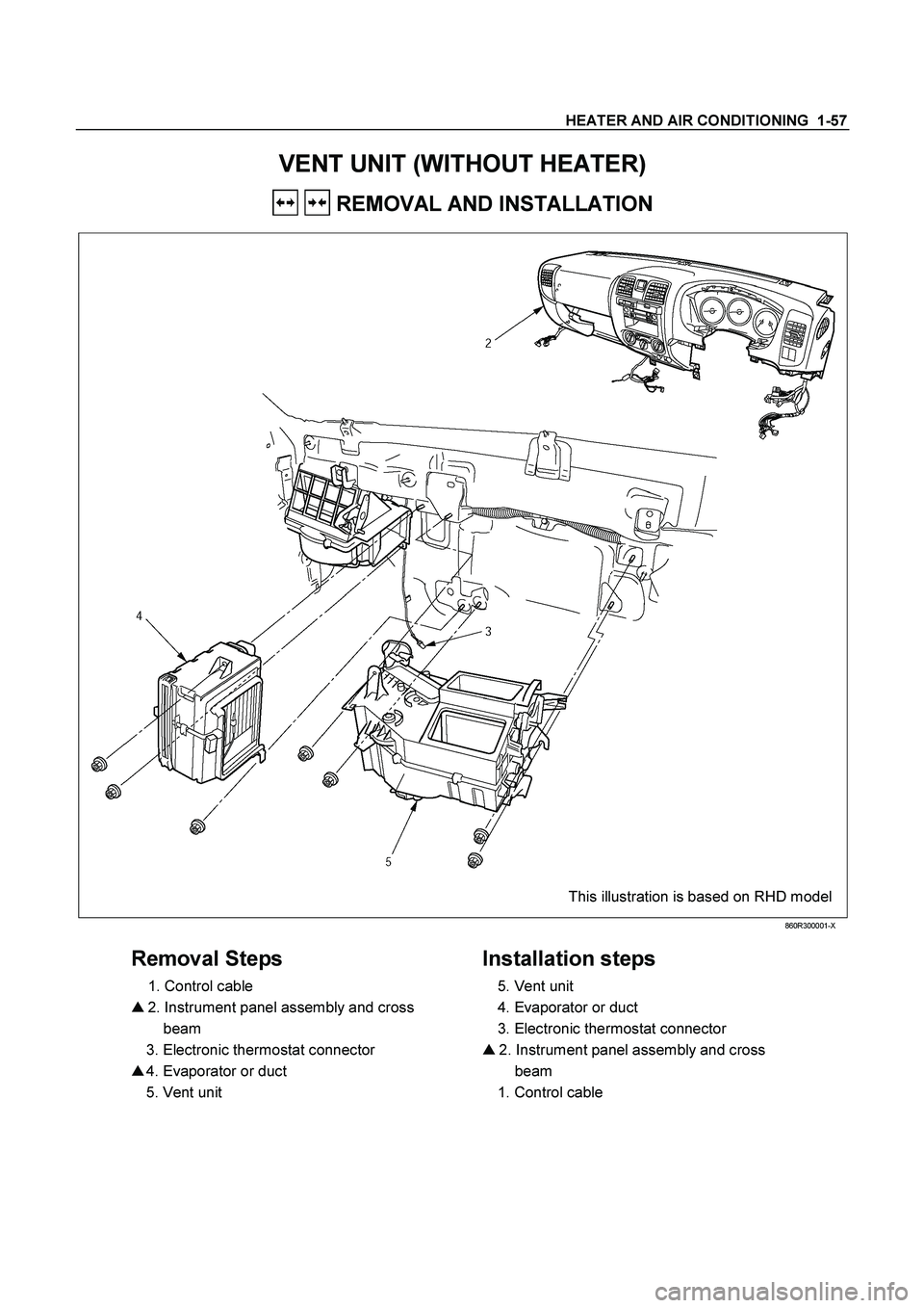
VENT UNIT (WITHOUT HEATER)
REMOVAL AND INSTALLATION
This illustration is based on RHD model
860R300001-X
Removal Steps
1. Control cable
� 2. Instrument panel assembly and cross
beam
3. Electronic thermostat connector
� 4. Evaporator or duct
5. Vent unit
Installation steps
5. Vent unit
4. Evaporator or duct
3. Electronic thermostat connector
� 2. Instrument panel assembly and cross
beam
1. Control cable