Page 932 of 4264
8A-274 ELECTRICAL-BODY AND CHASSIS
Terminal Connector No. B-23
No. C24SE
1
ABS CONT. (BRAKE)
2
�
3
�
4
�
5
�
6
�
7
�
8
�
9
BRAKE
10
CHARGE
11
TURN (RIGHT)
12
�
13
�
14
�
15
�
16
�
17
ILLUMI (-)
18
ILLUMI (+)
Terminal Connector No. B-24
No. C24SE
1
�
2
4LO
3
OIL PRESSURE
4
�
5
4WD
6
CHECK 4WD
7
�
8
�
9
SPEED (+)
10
4P OUTPUT
11
�
12
STARTER
13
TEMP
14
FUEL
15
FRONT FOG
16
�
17
CHECK ENGINE
18
AIR BAG
19
SEAT BELT
20
BEAM (+)
21
TURN (LEFT)
22
BEAM (-)
23
BEAM (+)
24
�
25
�
26
POWER GND
27
SPEED (-)
28
GND UNIT
29
+B
30
IGN
Page 933 of 4264
ELECTRICAL-BODY AND CHASSIS 8A-275
Connector No. B-23
Terminal Connector place SOUTH
AFRICA SAUDI
ARABIA ISRAEL EC UK OTHER
1
ABS CONT. (BRAKE)
2
CHECK TRANS
3
A/T-P
4
A/T-R
5
A/T-2
6
A/T-L
7
� � � � � � �
8
� � � � � � �
9
BRAKE
10
CHARGE
11
TURN (R)
12
A/T-N
13
A/T-D
14
A/T-3
15
DIFF. LOCK � � � � �
16
A/T OIL TEMP � �
17
ILL (-)
18
ILL (+)
RTW48AXF005901
Page 934 of 4264
8A-276 ELECTRICAL-BODY AND CHASSIS
Connector No. B-24
Terminal Connector place SOUTH
AFRICA SAUDI
ARABIA ISRAEL EC UK OTHER
1
SEDIMENTER
2
4LO
3
OIL PRESS
4
4WD
5
CHECK 4WD
6
GLOW
7
POWER DRIVE
8
� � � � � � �
9
SPEED (+)
10
4P OUTPUT
11
TACHO
12
STARTER
13
TEMP
14
FUEL
RR FOG � � � 15
FRONT FOG � � � � � �
16
ABS CONT. (ABS)
17
CHECK ENGINE
18
AIR BAG
SEAT BELT 19
LOW COOLANT � � � � �
CRUISE SET � � � � 20
BEAM (+) � �
�
21
TURN (LEFT)
22
BEAM (-)
BEAM (+) � � � 23
FRONT FOG � �
�
24
3rd START (A/T)
25
� � � � � � �
26
POWER GND
27
SPEED (-)
28
GND UNIT
29
+B
30
IGN
Page 994 of 4264
8A-336 ELECTRICAL-BODY AND CHASSIS
REMOVAL AND INSTALLATION
AUDIO
Refer to Section 9 “ACCESSORIES” for details.
CIGARETTE LIGHTER
Removal
1. Disconnect the battery ground cable.
2. Remove the center cluster ASM.
3. Remove the lighter
1.
4. Disconnect the connector
2.
5. Loosen the ring nut
3 at the back side.
6. Remove the outer case
4.
7. Remove the lighter holder
5 from the bezel.
Installation
Follow the removal procedure in the reverse order to install the
lighter.
Pay close attention to the important points mentioned in the
following paragraphs.
Connector
Be absolutely sure that the lighter connector is securely
connected.
This will prevent a poor contact and an open circuit.
ACC SOCKET
Removal
1. Disconnect the battery ground cable.
2. Remove the center cluster ASM.
3. Disconnect the connector.
4. Remove the holder nut
1.
5. Remove the ACC Socket
2
Installation
Follow the removal procedure in the reverse order to install the
lighter.
Page 1081 of 4264
ELECTRICAL-BODY AND CHASSIS 8A-423
No. Connector face No. Connector face
C-36
Silver
Engine room-LH ; Ground C-54
(6VE1)
(4JH1-TC)
OrangeABS sensor Front-LH
C-37
Black
Brake fluid level switch C-55
BrownThermo AMP
C-38
(4JH1-TC)
Vacuum switch C-56
(C24SE)
ECM
C-39
Parking brake switch (stick type) C-56
(4JA1-TC
4JH1-TC)
ECM-A
C-40
~
C-43 NOT USED C-57
(4JA1-TC
4JH1-TC)
ECM-B
C-44
White
Stop lamp switch C-58
~
C-62 NOT USED
C-45
~
C-49 NOT USED C-63
(6VE1)
(4JH1-TC)
Gray Front Fog lamp-RH
C-50
Condenser fan C-64
(6VE1)
(4JH1-TC)
Gray Front Fog lamp-LH
C-51
~
C-52 NOT USED C-65
~
C-66 NOT USED
C-53
(6VE1)
(4JH1-TC)
Orange ABS sensor Front-RH C-67
(6VE1)
(4JH1-TC)
BlackEHCU
Page 1090 of 4264
8A-432 ELECTRICAL-BODY AND CHASSIS
No. Connector face No. Connector face
F-1
White
Fuel filter
F-2
White
Fuel pump & sensor
F-3
NOT USED
F-4
Gray
ABS sensor
F-5
Gray
Rear combination lamp-RH
F-6
Gray
Rear combination lamp-LH
F-7
Gray
License plate lamp
F-8
Black
Rear fog light – RH
F-9
Black
Rear fog light - LH
Page 1162 of 4264

6A – 22 ENGINE MECHANICAL
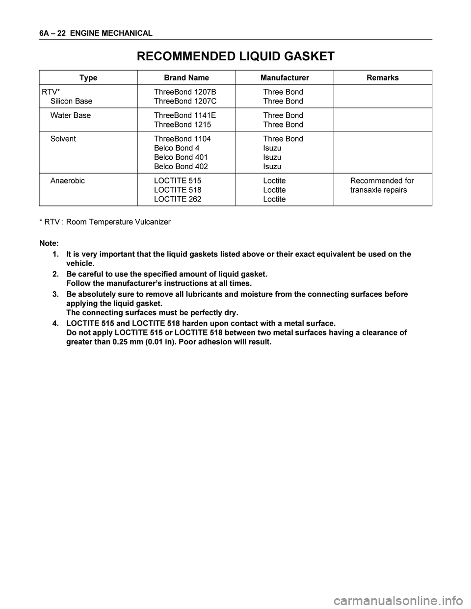
RECOMMENDED LIQUID GASKET
Type Brand Name Manufacturer Remarks
RTV*
Silicon Base ThreeBond 1207B
ThreeBond 1207C Three Bond
Three Bond
Water Base ThreeBond 1141E
ThreeBond 1215 Three Bond
Three Bond
Solvent ThreeBond 1104
Belco Bond 4
Belco Bond 401
Belco Bond 402 Three Bond
Isuzu
Isuzu
Isuzu
Anaerobic LOCTITE 515
LOCTITE 518
LOCTITE 262 Loctite
Loctite
Loctite Recommended for
transaxle repairs
* RTV : Room Temperature Vulcanizer
Note:
1. It is very important that the liquid gaskets listed above or their exact equivalent be used on the
vehicle.
2. Be careful to use the specified amount of liquid gasket.
Follow the manufacturer’s instructions at all times.
3. Be absolutely sure to remove all lubricants and moisture from the connecting surfaces before
applying the liquid gasket.
The connecting surfaces must be perfectly dry.
4. LOCTITE 515 and LOCTITE 518 harden upon contact with a metal surface.
Do not apply LOCTITE 515 or LOCTITE 518 between two metal surfaces having a clearance of
greater than 0.25 mm (0.01 in). Poor adhesion will result.
Page 1264 of 4264

6A – 124 ENGINE MECHANICAL
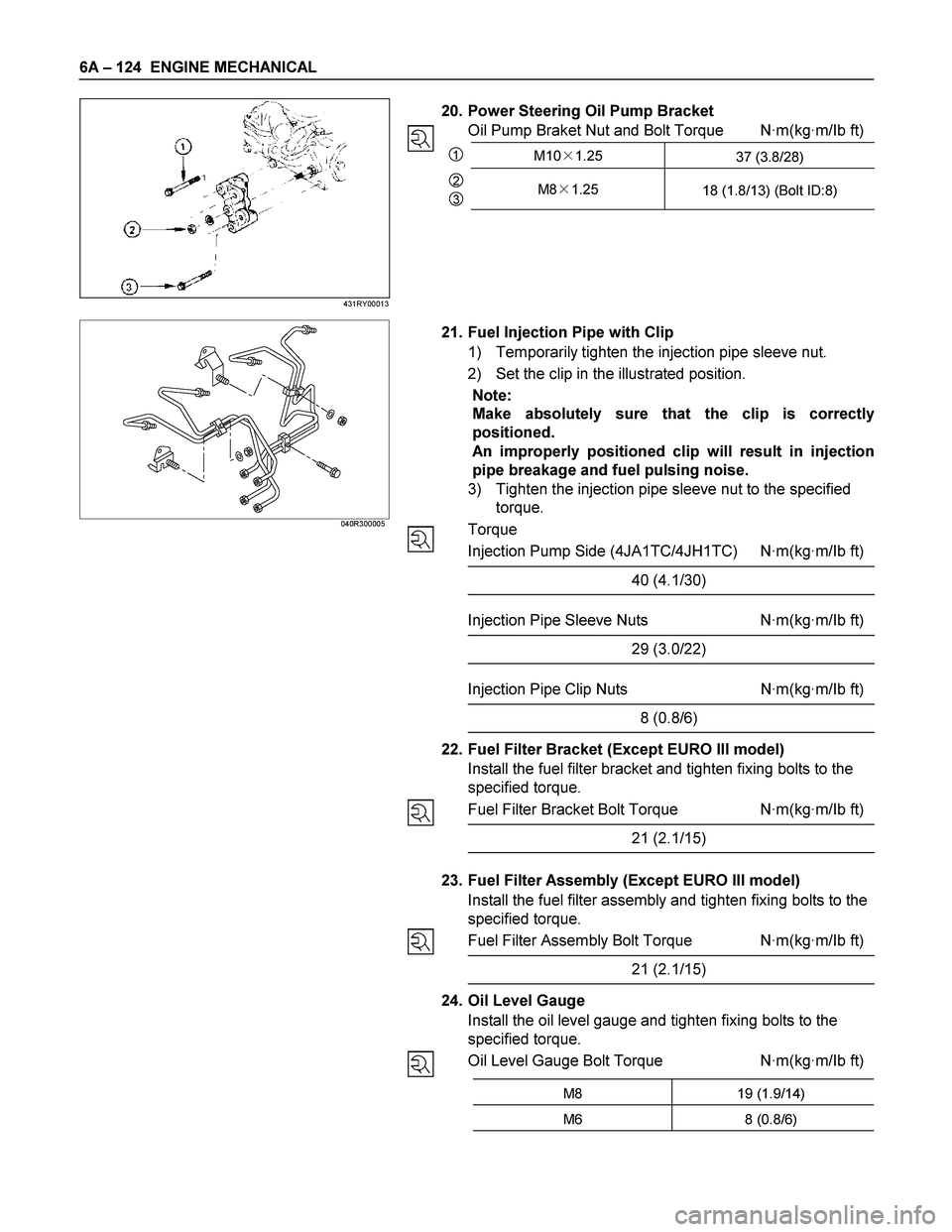
20. Power Steering Oil Pump Bracket
Oil Pump Braket Nut and Bolt Torque N·m(kg·m/Ib ft)
1M10�1.25
37 (3.8/28)
2
3M8�1.25
18 (1.8/13) (Bolt ID:8)
040R300005
21. Fuel Injection Pipe with Clip
1) Temporarily tighten the injection pipe sleeve nut.
2) Set the clip in the illustrated position.
Note:
Make absolutely sure that the clip is correctly
positioned.
An improperly positioned clip will result in injection
pipe breakage and fuel pulsing noise.
3) Tighten the injection pipe sleeve nut to the specified
torque.
Torque
Injection Pump Side (4JA1TC/4JH1TC) N·m(kg·m/Ib ft)
40 (4.1/30)
Injection Pipe Sleeve Nuts N·m(kg·m/Ib ft)
29 (3.0/22)
Injection Pipe Clip Nuts N·m(kg·m/Ib ft)
8 (0.8/6)
22. Fuel Filter Bracket (Except EURO III model)
Install the fuel filter bracket and tighten fixing bolts to the
specified torque.
Fuel Filter Bracket Bolt Torque N·m(kg·m/Ib ft)
21 (2.1/15)
23. Fuel Filter Assembly (Except EURO III model)
Install the fuel filter assembly and tighten fixing bolts to the
specified torque.
Fuel Filter Assembly Bolt Torque N·m(kg·m/Ib ft)
21 (2.1/15)
24. Oil Level Gauge
Install the oil level gauge and tighten fixing bolts to the
specified torque.
Oil Level Gauge Bolt Torque N·m(kg·m/Ib ft)
M8 19 (1.9/14)
M6 8 (0.8/6)
431RY00013