Page 690 of 4264

8A-32 ELECTRICAL-BODY AND CHASSIS
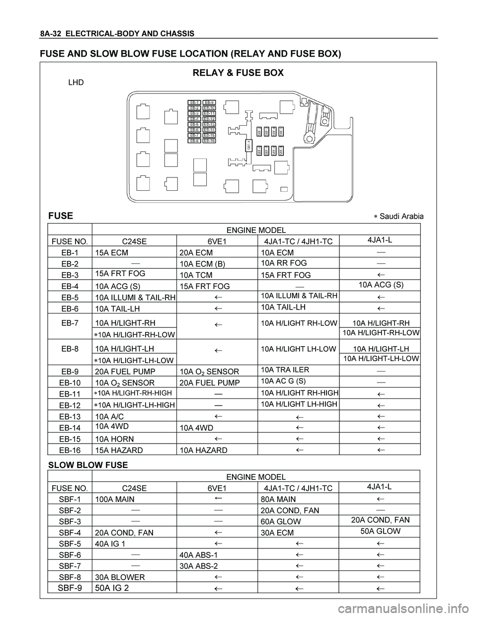
FUSE AND SLOW BLOW FUSE LOCATION (RELAY AND FUSE BOX)
RELAY & FUSE BOX
LHD
FUSE � Saudi Arabia
ENGINE MODEL
FUSE NO. C24SE 6VE1 4JA1-TC / 4JH1-TC4JA1-L
EB-1 15A ECM 20A ECM 10A ECM �
EB-2 �
10A ECM (B) 10A RR FOG �
EB-3 15A FRT FOG
10A TCM 15A FRT FOG �
EB-4 10A ACG (S) 15A FRT FOG � 10A ACG (S)
EB-5 10A ILLUMI & TAIL-RH � 10A ILLUMI & TAIL-RH �
EB-6 10A TAIL-LH � 10A TAIL-LH
�
EB-7 10A H/LIGHT-RH 10A H/LIGHT-RH
�10A H/LIGHT-RH-LOW
� 10A H/LIGHT RH-LOW
10A H/LIGHT-RH-LOW
EB-8 10A H/LIGHT-LH 10A H/LIGHT-LH
�10A H/LIGHT-LH-LOW
� 10A H/LIGHT LH-LOW
10A H/LIGHT-LH-LOW
EB-9 20A FUEL PUMP 10A O2 SENSOR 10A TRA ILER �
EB-10 10A O2 SENSOR 20A FUEL PUMP 10A AC G (S) �
EB-11 �10A H/LIGHT-RH-HIGH � 10A H/LIGHT RH-HIGH �
EB-12 �10A H/LIGHT-LH-HIGH � 10A H/LIGHT LH-HIGH �
EB-13 10A A/C �
� �
EB-14 10A 4WD
10A 4WD � �
EB-15 10A HORN � � �
EB-16 15A HAZARD 10A HAZARD � �
SLOW BLOW FUSE
ENGINE MODEL
FUSE NO. C24SE 6VE1 4JA1-TC / 4JH1-TC4JA1-L
SBF-1 100A MAIN �
80A MAIN �
SBF-2 � �
20A COND, FAN �
SBF-3 � �
60A GLOW 20A COND, FAN
SBF-4 20A COND, FAN �
30A ECM 50A GLOW
SBF-5 40A IG 1 � � �
SBF-6 �
40A ABS-1 � �
SBF-7 �
30A ABS-2 � �
SBF-8 30A BLOWER � � �
SBF-9 50A IG 2 � � �
Page 763 of 4264
ELECTRICAL-BODY AND CHASSIS 8A-105
REMOVAL AND INSTALLATION
ECM (ENGINE CONTROL MODULE):
C24SE
Removal
1. Lift both the ECM harness connector locking levers and
remove the two harness connectors form the ECM.
2. Remove the four socket head screws securing the ECM to
the mounting bracket.
3. Remove the ECM from the engine compartment
.
4. Pull out the ECM.
5. Disconnect both red and tan connectors.
Refer to the Section 6E-ENGINE of this Manual.
IMPORTANT: The replacement ECM must be programmed.
“SPS (Service Programming System) and immobiliser
programming (if equipped) is/are necessary”
Installation
Follow the removal procedure in the reverse order to install the
ECM.
Pay close attention to the important points mentioned in the
following paragraphs.
Connector
Be absolutely sure that ECM is securely connected.
This will prevent a poor contact and open circuit.
Page 764 of 4264
8A-106 ELECTRICAL-BODY AND CHASSIS
REMOVAL AND INSTALLATION
ECM (ENGINE CONTROL MODULE):
6VE1
Removal
1. Pull both the red ECM harness connector locks toward the
front of the vehicle, and remove the two harness connectors
form the ECM.
2. Remove the four hex-head screws securing the ECM to the
common chamber.
3. Remove the ECM from the engine compartment.
4. Pull out the ECM.
5. Disconnect both red and tan connectors.
Refer to the Section 6E-ENGINE of this Manual.
IMPORTANT: The replacement ECM must be programmed.
“SPS (Service Programming System) and immobiliser
programming (if equipped) is/are necessary”
Installation
Follow the removal procedure in the reverse order to install the
ECM.
Pay close attention to the important points mentioned in the
following paragraphs.
Connector
Be absolutely sure that ECM is securely connected.
This will prevent a poor contact and open circuit.
Page 765 of 4264

ELECTRICAL-BODY AND CHASSIS 8A-107
REMOVAL AND INSTALLATION
ECM (ENGINE CONTROL MODULE):
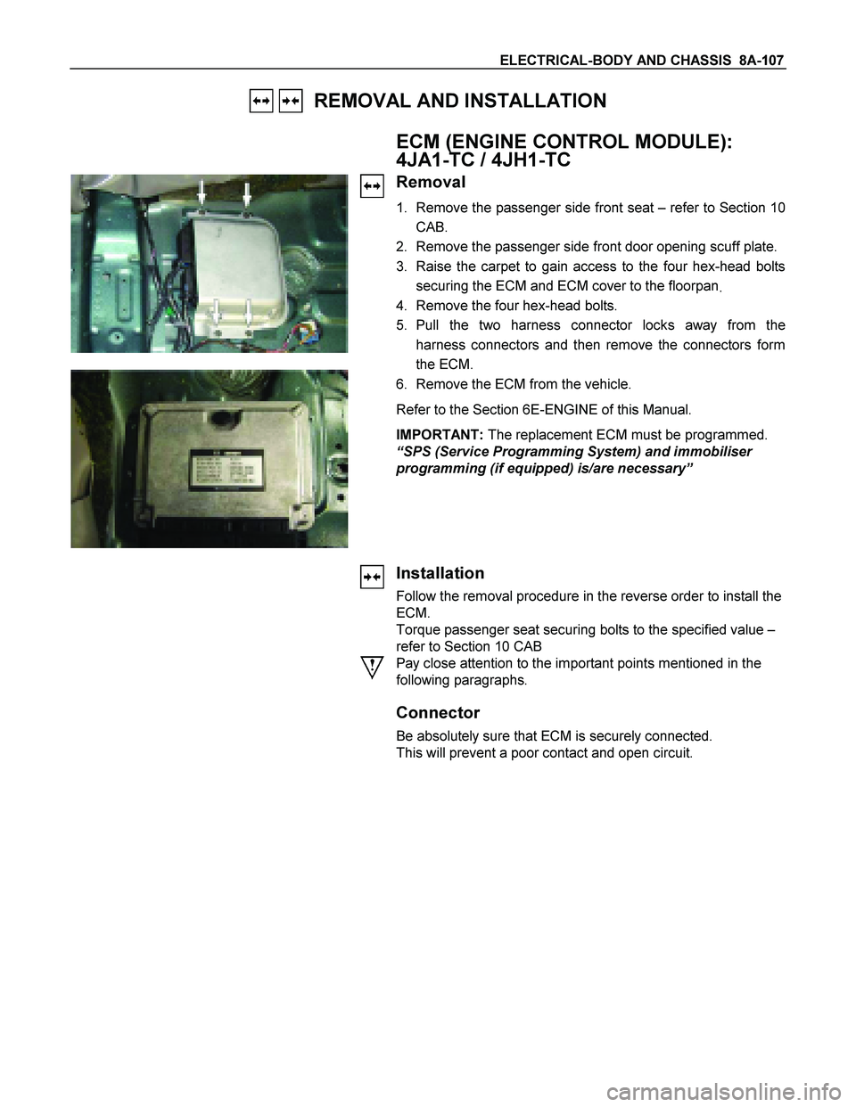
4JA1-TC / 4JH1-TC
Removal
1. Remove the passenger side front seat – refer to Section 10
CAB.
2. Remove the passenger side front door opening scuff plate.
3. Raise the carpet to gain access to the four hex-head bolts
securing the ECM and ECM cover to the floorpan
.
4. Remove the four hex-head bolts.
5. Pull the two harness connector locks away from the
harness connectors and then remove the connectors form
the ECM.
6. Remove the ECM from the vehicle.
Refer to the Section 6E-ENGINE of this Manual.
IMPORTANT: The replacement ECM must be programmed.
“SPS (Service Programming System) and immobiliser
programming (if equipped) is/are necessary”
Installation
Follow the removal procedure in the reverse order to install the
ECM.
Torque passenger seat securing bolts to the specified value –
refer to Section 10 CAB
Pay close attention to the important points mentioned in the
following paragraphs.
Connector
Be absolutely sure that ECM is securely connected.
This will prevent a poor contact and open circuit.
Page 766 of 4264
8A-108 ELECTRICAL-BODY AND CHASSIS
REMOVAL AND INSTALLATION
FUEL PUMP
Removal
1. Remove the fuel tank.
Refer to the Section 6C-ENGINE FUEL of this Manual.
� Disconnect the fuel pipe.
Installation
Follow the removal procedure in the reverse order to install the
fuel pump.
Pay close attention to the important points mentioned in the
following paragraphs.
Rubber Seal
Be absolutely sure that the fuel pump rubber seals correctly
seated.
Connector
Be absolutely sure that the fuel pump connector is securely
connected.
This will prevent a poor contact and an open circuit.
Page 787 of 4264

ELECTRICAL-BODY AND CHASSIS 8A-129
Installation
Follow the removal procedure in the reverse order to install the
headlight.
Pay close attention to the important points mentioned in the
following paragraphs.
Connector
Be absolutely sure that the headlight connector is securely
connected.
This will prevent a contact and an open circuit.
This illustration is based on RHD model
LIGHTING SWITCH
Removal
1. Disconnect the battery ground cable.
2. Remove the steering wheel
1.
Refer to the “STEERING” Section of this manual.
3. Remove the Instrument panel lower cover
2.
4. Remove the steering column cover
3.
This illustration is based on RHD model
5. Disconnect the connector.
6. Remove the lighting switch from the steering shaft.
Installation
Follow the removal procedure in the reverse order to install the
lighting switch.
Pay close attention to the important points mentioned in the
following paragraphs.
Connector
Be absolutely sure that the lighting switch connector is securely
connected.
This will prevent a poor contact and an open circuit.
Wire Harness
Do not pinch the wire harnesses between the cluster and the
meter hood during the cluster installation procedure.
Wire damage will result.
Page 788 of 4264

8A-130 ELECTRICAL-BODY AND CHASSIS
FRONT TURN LIGHT
Removal
RTW38DSH000601
1. Turn the socket counterclockwise to disconnect it from the
front turn light housing.
2. Pull the bulb from the socket.
Installation
Follow the removal procedure in the reverse order to install the
front turn light.
Pay close attention to the important points mentioned in the
following paragraphs.
Connector
Be absolutely sure that the clearance light connector is
securely connected.
This will prevent a poor contact and an open circuit.
CLEARANCE LIGHT
Removal
RTW38DSH000601
1. Turn the socket counterclockwise to disconnect it from the
clearance light housing.
2. Pull the bulb from the socket.
Installation
Follow the removal procedure in the reverse order to install the
clearance light.
Pay close attention to the important points mentioned in the
following paragraphs.
Connector
Be absolutely sure that the clearance light connector is
securely connected.
This will prevent a poor contact and an open circuit.
Page 789 of 4264

ELECTRICAL-BODY AND CHASSIS 8A-131
LICENSE PLATE LIGHT
Removal
1. Remove the lens cover 1 and the connector 2.
2. Pull the bulb
3 to remove it.
Installation
Follow the removal procedure in the reverse order to install the
license plate light.
Pay close attention to the important points mentioned in the
following paragraphs.
Bulb
Be absolutely sure that the license plate light bulb is correctly
installed.
This will prevent a poor contact and open circuit.
HEADLIGHT BEAM SWITCH
(COMBINATION SWITCH)
Removal
1. Disconnect the battery ground cable.
2. Remove the screws on the lower part of the steering wheel.
3. Remove the horn pad.
4. Remove the wiring connector.
5. Remove the steering wheel fixing nuts.
6. Remove the steering wheel.
Refer to the "STEERING" Section of this manual.
7. Remove the Instrument panel lower cover.
8. Remove the steering column cover.
9. Disconnect the connector.
10. Remove the headlight beam switch (lever) from the steering
shaft (combination switch).
Installation
Follow the removal procedure in the reverse order to install the
headlight beam switch (lever).
Pay close attention to the important points mentioned in the
following paragraphs.
Connector
Be absolutely sure that the headlight beam switch connector is
securely connected.
This will prevent a poor contact and an open circuit.