Page 2477 of 4264
ENGINE MECHANICAL (C24SE) 6A-57
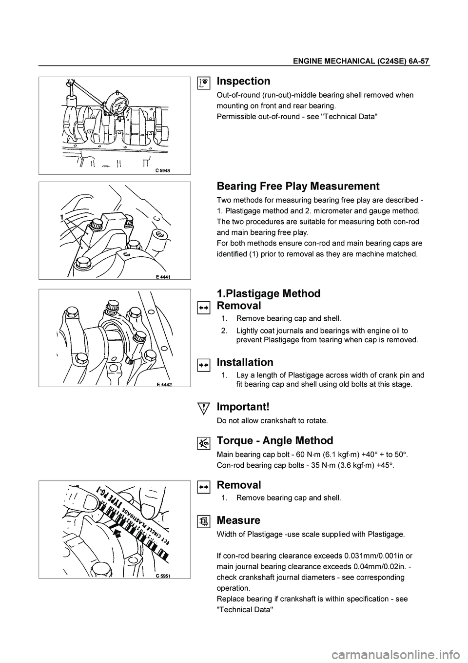
Inspection
Out-of-round (run-out)-middle bearing shell removed when
mounting on front and rear bearing.
Permissible out-of-round - see "Technical Data"
Bearing Free Play Measurement
Two methods for measuring bearing free play are described -
1. Plastigage method and 2. micrometer and gauge method.
The two procedures are suitable for measuring both con-rod
and main bearing free play.
For both methods ensure con-rod and main bearing caps are
identified (1) prior to removal as they are machine matched.
1.Plastigage Method
Removal
1. Remove bearing cap and shell.
2. Lightly coat journals and bearings with engine oil to
prevent Plastigage from tearing when cap is removed.
Installation
1. Lay a length of Plastigage across width of crank pin and
fit bearing cap and shell using old bolts at this stage.
Important!
Do not allow crankshaft to rotate.
Torque - Angle Method
Main bearing cap bolt - 60 N�
m (6.1 kgf�
m) +40�
+ to 50�
.
Con-rod bearing cap bolts - 35 N�
m (3.6 kgf�
m) +45�
.
Removal
1. Remove bearing cap and shell.
Measure
Width of Plastigage -use scale supplied with Plastigage.
If con-rod bearing clearance exceeds 0.031mm/0.001in or
main journal bearing clearance exceeds 0.04mm/0.02in. -
check crankshaft journal diameters - see corresponding
operation.
Replace bearing if crankshaft is within specification - see
"Technical Data"
Page 2478 of 4264
6A-58 ENGINE MECHANICAL (C24SE)
Clean
Plastigage from journals.
Lightly coat journals and bearings with engine oil.
Installation
Install bearing cap and shell using new bolts.
Torque - Angle Method
Main bearing cap bolt - 60 N�
m (6.1 kgf�
m) +40�
to 50�
.
Con-rod bearing cap bolts - 35 N�
m (3.9 kgf�
m) +45�
.
2.Micrometer and gauge method.
Crankshaft removed.
Installation
1. Install caps and bearing shells to con-rods and cylinder
block.
Measure
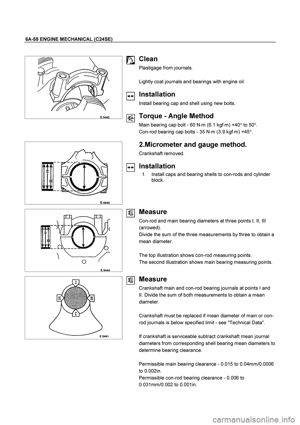
Con-rod and main bearing diameters at three points I, II, III
(arrowed).
Divide the sum of the three measurements by three to obtain a
mean diameter.
The top illustration shows con-rod measuring points.
The second illustration shows main bearing measuring points.
Measure
Crankshaft main and con-rod bearing journals at points I and
II. Divide the sum of both measurements to obtain a mean
diameter.
Crankshaft must be replaced if mean diameter of main or con-
rod journals is below specified limit - see "Technical Data".
If crankshaft is serviceable subtract crankshaft mean journal
diameters from corresponding shell bearing mean diameters to
determine bearing clearance.
Permissible main bearing clearance - 0.015 to 0.04mm/0.0006
to 0.002in.
Permissible con-rod bearing clearance - 0.006 to
0.031mm/0.002 to 0.001in.
Page 2479 of 4264
ENGINE MECHANICAL (C24SE) 6A-59
Bypass Valve
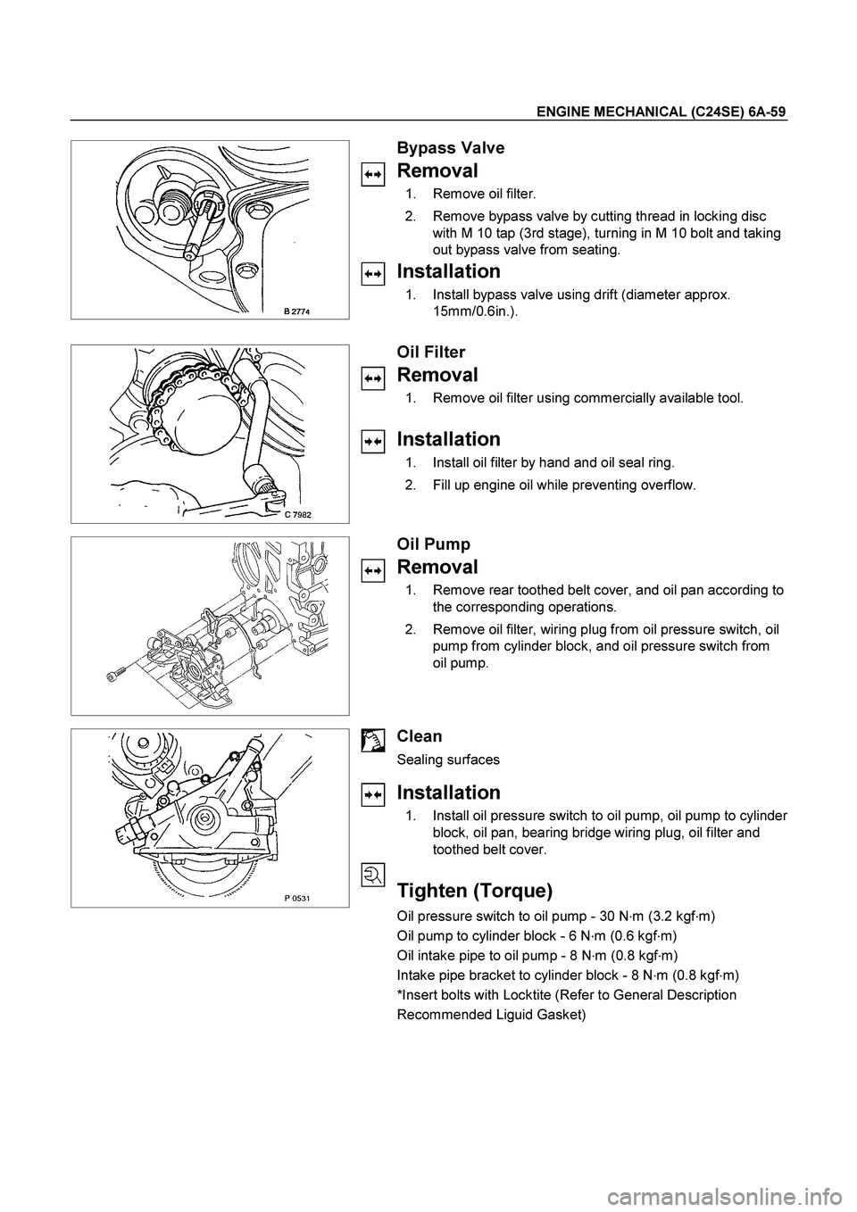
Removal
1. Remove oil filter.
2. Remove bypass valve by cutting thread in locking disc
with M 10 tap (3rd stage), turning in M 10 bolt and taking
out bypass valve from seating.
Installation
1. Install bypass valve using drift (diameter approx.
15mm/0.6in.).
Oil Filter
Removal
1. Remove oil filter using commercially available tool.
Installation
1. Install oil filter by hand and oil seal ring.
2. Fill up engine oil while preventing overflow.
Oil Pump
Removal
1. Remove rear toothed belt cover, and oil pan according to
the corresponding operations.
2. Remove oil filter, wiring plug from oil pressure switch, oil
pump from cylinder block, and oil pressure switch from
oil pump.
Clean
Sealing surfaces
Installation
1. Install oil pressure switch to oil pump, oil pump to cylinder
block, oil pan, bearing bridge wiring plug, oil filter and
toothed belt cover.
Tighten (Torque)
Oil pressure switch to oil pump - 30 N�
m (3.2 kgf�
m)
Oil pump to cylinder block - 6 N�
m (0.6 kgf�
m)
Oil intake pipe to oil pump - 8 N�
m (0.8 kgf�
m)
Intake pipe bracket to cylinder block - 8 N�
m (0.8 kgf�
m)
*Insert bolts with Locktite (Refer to General Description
Recommended Liguid Gasket)
Page 2480 of 4264
6A-60 ENGINE MECHANICAL (C24SE)
Oil Pump Safety Valve
Removal
1. Remove closure plug.
2. Remove seal ring.
3. Remove spring.
4. Remove piston.
Installation
1. Install piston (observe installation position).
2. Install spring.
3. Install seal ring.
4. Install closure plug.
Tighten (Torque)
Closure plug - 30 N�
m (3.0 kgf�
m)
Oil Pump (Overhaul)
Removal
1. Remove oil pump according to the corresponding
operation.
2. Remove oil cover and pressure control valve.
Inspect
Clearance between gear pair and housing upper edge - see
“Technical Data”.
Check housing, cover and pressure control valve.
Installation
1. Install pump cover with Sealing Compound 15 03 166 (90
094 714).
2. Install oil pump safety valve according to the
corresponding operation.
3. Install oil pump according to the corresponding operation.
Page 2481 of 4264
ENGINE MECHANICAL (C24SE) 6A-61
OPERATIONS ON OIL CIRCULATION
Cylinder Head Safety Valve
Removal
1. Remove cylinder head according to the corresponding
operation.
2. Make hole in core plugs with pointed drift, turn in self
tapping screw and edge out.
Important!
Cover oil duct in cylinder head with piece of cloth.
3. Pull out valve retainer, using commercially available tool.
4. Remove ball and spring.
5. Cut three threads in the ball seating with M 10 tap (3rd
stage).
6. Coat tap with grease.
7. Remove ball seating from cylinder head with
commercially available tool.
Do not damage cylinder head.
Page 2486 of 4264
6A-66 ENGINE MECHANICAL (C24SE)
Installation
Follow the removal procedure in the reverse order to install the
radiator.
Thermostat
Removal
1. Remove water outlet nozzles with thermostat from
thermostat housing.
2. Remove coolant hose and collect coolant.
Important!
Remove and Install thermostat only together with water outlet
nozzles.
Tighten (Torque)
Water outlet nozzles to thermostat housing - 8 N�
m (0.8 kgf�
m)
Installation
1. Install coolant hose.
2. Fill cooling system and bleed according to the
corresponding operation.
Water Pump
Removal
1. Remove lower hose band from pipe band and collect
coolant.
2. Remove front toothed belt cover according to the
corresponding operation.
3. Remove water pump from cylinder block after releasing
tension on toothed belt.
Clean
Sealing surfaces
Page 2487 of 4264
ENGINE MECHANICAL (C24SE) 6A-67
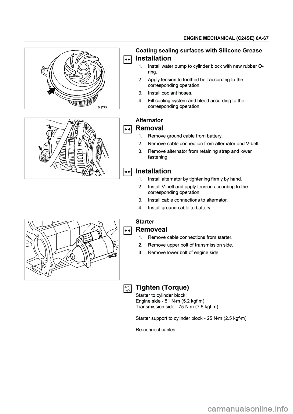
Coating sealing surfaces with Silicone Grease
Installation
1. Install water pump to cylinder block with new rubber O-
ring.
2. Apply tension to toothed belt according to the
corresponding operation.
3. Install coolant hoses.
4. Fill cooling system and bleed according to the
corresponding operation.
Alternator
Removal
1. Remove ground cable from battery.
2. Remove cable connection from alternator and V-belt.
3. Remove alternator from retaining strap and lower
fastening.
Installation
1. Install alternator by tightening firmly by hand.
2. Install V-belt and apply tension according to the
corresponding operation.
3. Install cable connections to alternator.
4. Install ground cable to battery.
Starter
Removeal
1. Remove cable connections from starter.
2. Remove upper bolt of transmission side.
3. Remove lower bolt of engine side.
Tighten (Torque)
Starter to cylinder block:
Engine side - 51 N�
m (5.2 kgf�
m)
Transmission side - 75 N�
m (7.6 kgf�
m)
Starter support to cylinder block - 25 N�
m (2.5 kgf�
m)
Re-connect cables.
Page 2528 of 4264
6C-4 ENGINE FUEL (C24SE)
Fuel Metering
Engine Control Module (ECM) is in complete control of this fuel
delivery system during normal driving conditions.
The intake manifold function, like that of a diesel, is used only
to let air into the engine. The fuel is injected by separate
injectors that are mounted over the intake manifold.
The Manifold Absolute Pressure (MAP) sensor measures the
changes in the intake manifold pressure which result from
engine load and speed changes, which the MAP senso
r
converts to a voltage output.
This sensor generates the voltage to change corresponding to
the flow of the air drawn into the engine.
The changing voltage is transformed into an electric signal and
provided to the ECM.
With receipt of the signals sent from the MAP sensor, Intake
Air Temperature sensor and others, the ECM determines an
appropriate fuel injection pulse width feeding such information
to the fuel injector valves to effect an appropriate air/fuel ratio.
The Multiport Fuel Injection system utilizes an injection system
where the injectors turn on at every crankshaft revolution. The
ECM controls the injector on time so that the correct amount o
f
fuel is metered depending on driving conditions.
Two interchangeable "O" rings are used on the injector tha
t
must be replaced when the injectors are removed.
The fuel rail is attached to the top of the intake manifold and
supplies fuel to all the injectors.
Fuel is recirculated through the rail continually while the engine
is running. This removes air and vapors from the fuel as well
as keeping the fuel cool during hot weather operation.
The fuel pressure control valve that is mounted on the fuel rail
maintains a pressure differential across the injectors under all
operating conditions. It is accomplished by controlling the
amount of fuel that is recirculated back to the fuel tank based
on engine demand.
See Section "Driveability and Emission" for more information
and diagnosis.