Page 2359 of 4264

3.5L ENGINE DRIVEABILITY AND EMISSIONS 6E-363
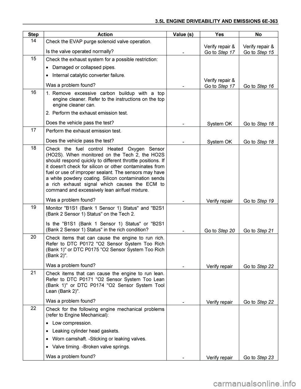
Step Action Value (s) Yes No
14
Check the EVAP purge solenoid valve operation.
Is the valve operated normally?
- Verify repair &
Go to Step 17 Verify repair &
Go to Step 15
15
Check the exhaust system for a possible restriction:
� Damaged or collapsed pipes.
� Internal catalytic converter failure.
Was a problem found?
- Verify repair &
Go to Step 17 Go to Step 16
16
1. Remove excessive carbon buildup with a top
engine cleaner. Refer to the instructions on the top
engine cleaner can.
2. Perform the exhaust emission test.
Does the vehicle pass the test?
- System OK Go to Step 18
17
Perform the exhaust emission test.
Does the vehicle pass the test?
- System OK Go to Step 18
18
Check the fuel control Heated Oxygen Sensor
(HO2S). When monitored on the Tech 2, the HO2S
should respond quickly to different throttle positions. If
it doesn't check for silicon or other contaminates from
fuel or use of improper sealant. The sensors may have
a white powdery coating. Silicon contamination sends
a rich exhaust signal which causes the ECM to
command and excessively lean air/fuel mixture.
Was a problem found?
- Verify repair Go to Step 19
19
Monitor "B1S1 (Bank 1 Sensor 1) Status" and "B2S1
(Bank 2 Sensor 1) Status" on the Tech 2.
Is the "B1S1 (Bank 1 Sensor 1) Status" or "B2S1
(Bank 2 Sensor 1) Status" in the rich condition?
- Go to Step 20 Go to Step 21
20
Check items that can cause the engine to run rich.
Refer to DTC P0172 "O2 Sensor System Too Rich
(Bank 1)" or DTC P0175 "O2 Sensor System Too Rich
(Bank 2)".
Was a problem found?
- Verify repair Go to Step 22
21
Check items that can cause the engine to run lean.
Refer to DTC P0171 "O2 Sensor System Too Lean
(Bank 1)" or DTC P0174 "O2 Sensor System Tool
Lean (Bank 2)".
Was a problem found?
- Verify repair Go to Step 22
22
Check for the following engine mechanical problems
(refer to Engine Mechanical):
� Low compression.
� Leaking cylinder head gaskets.
� Worn camshaft. -Sticking or leaking valves.
� Valve timing. -Broken valve springs.
Was a problem found?
- Verify repair Go to Step 23
Page 2440 of 4264
6A-20 ENGINE MECHANICAL (C24SE)
6. Install power steering pump and V-belt.
Adjust
Adjust power steering pump V-belt tension according to the
corresponding operation.
Installation
7. Install radiator according to the corresponding operation.
8. Install air inlet hose.
9. Install all electrical cable connections, hoses and lines to
engine.
10. Install accelerator cable from inlet pipe.
11. Install bonnet.
Inspection
1. Check engine oil level.
2. Fill up cooling system and bleed according to the
corresponding operation.
Page 2446 of 4264
6A-26 ENGINE MECHANICAL (C24SE)
OPERATIONS ON INSTALLED ENGINE
SEALING OPERATIONS
Gasket, Exhaust Manifold, Cylinder Head
Removal
1. Remove front exhaust pipe from exhaust manifold.
2. Remove exhaust manifold heat shield.
3. Remove exhaust manifold retaining nut.
4. Remove exhaust manifold from cylinder head.
Clean
Sealing surfaces.
Tighten (Torque)
Exhaust manifold to cylinder head - 22 N�
m (2.2 kgf�
m)
Front exhaust pipe to exhaust manifold - 25 N�
m (2.6 kgf�
m)
Gasket, Intake Manifold, Cylinder Head
Removal
1. Remove air intake hose.
2. Remove drive belt for alternator.
3. Remove bolt clamping bracket for alternator from intake
manifold.
4. Remove intake manifold from cylinder head.
Clean
Sealing surfaces
Tighten (Torque)
Intake manifold to cylinder head - 22 N�
m (2.2 kgf�
m)
Clamping bracket for alternator to intake manifold - 25 N�
m (2.5
kgf�
m)
Installation
1. Install V-belt according to the corresponding operation.
2. Install air intake hose.
Page 2447 of 4264

ENGINE MECHANICAL (C24SE) 6A-27
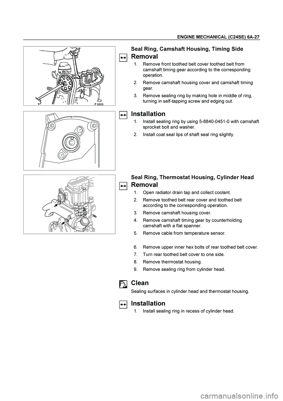
Seal Ring, Camshaft Housing, Timing Side
Removal
1. Remove front toothed belt cover toothed belt from
camshaft timing gear according to the corresponding
operation.
2. Remove camshaft housing cover and camshaft timing
gear.
3. Remove sealing ring by making hole in middle of ring,
turning in self-tapping screw and edging out.
Installation
1. Install sealing ring by using 5-8840-0451-0 with camshaft
sprocket bolt and washer.
2. Install coat seal lips of shaft seal ring slightly.
Seal Ring, Thermostat Housing, Cylinder Head
Removal
1. Open radiator drain tap and collect coolant.
2. Remove toothed belt rear cover and toothed belt
according to the corresponding operation.
3. Remove camshaft housing cover.
4. Remove camshaft timing gear by counterholding
camshaft with a flat spanner.
5. Remove cable from temperature sensor.
6. Remove upper inner hex bolts of rear toothed belt cover.
7. Turn rear toothed belt cover to one side.
8. Remove thermostat housing.
9. Remove sealing ring from cylinder head.
Clean
Sealing surfaces in cylinder head and thermostat housing.
Installation
1. Install sealing ring in recess of cylinder head.
Page 2448 of 4264
6A-28 ENGINE MECHANICAL (C24SE)
2. Install cable to temperature sensor.
3. Install upper bolts of rear toothed belt rear cover.
4. Install camshaft timing gear then check timing according
to the corresponding operation.
5. Install camshaft housing cover.
6. Install toothed belt and front cover.
7. Fill up and bleed cooling system according to the
corresponding operation.
Tighten (Torque)
Thermostat housing to cylinder head - 15 N�m/1.5 kgf�m.
Seal Ring - Front Camshaft Housing, Replace
Removal
Mark running direction of toothed belt.
Remove toothed belt-see operation “Toothed Belt, Replace”.
Camshaft housing cover, camshaft pulley-counterhold on hex
of camshaft.
Removal
Screw self-tapping screw into seal ring.
Edge out seal ring.
Installation
Lightly coat sealing lip of seal ring with protective grease.
Install seal ring with 5-8840-0451-0 into camshaft housing-use
screw and washer of camshaft pulley.
Page 2454 of 4264
6A-34 ENGINE MECHANICAL (C24SE)
OPERATIONS ON CYLINDER HEAD AND CAMSHAFT
HOUSING
Camshaft
Removal
1. Remove cylinder head according to the corresponding
operation.
2. Remove camshaft housing from cylinder head and lay
housing on base provided
3. Remove rear sealing gasket and plate camshaft housing
with taking care not to damage housing.
4. Remove thrust plate.
5. Remove camshaft.
6. Remove front sealing gasket and plate from camshaft
housing with taking care not to damage housing.
Inspection
All parts.
Installation
1. Install camshaft.
2. Coat sliding surfaces with molybdenum disulphate paste.
Tighten (Torque)
Thrust plate for camshaft housing - 8 N�
m (0.8 kgf�
m)
Page 2455 of 4264

ENGINE MECHANICAL (C24SE) 6A-35
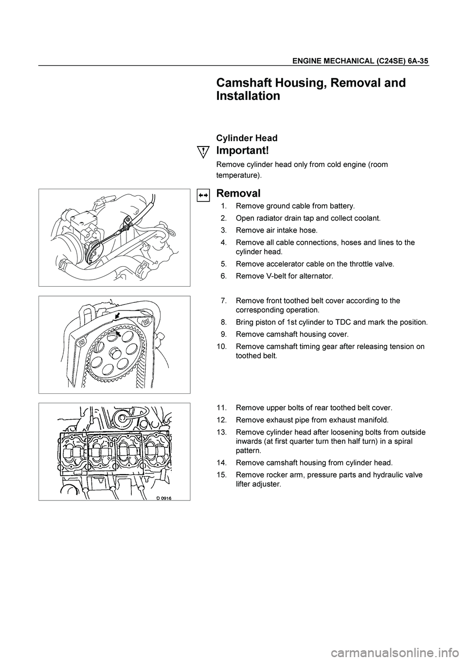
Camshaft Housing, Removal and
Installation
Cylinder Head
Important!
Remove cylinder head only from cold engine (room
temperature).
Removal
1. Remove ground cable from battery.
2. Open radiator drain tap and collect coolant.
3. Remove air intake hose.
4. Remove all cable connections, hoses and lines to the
cylinder head.
5. Remove accelerator cable on the throttle valve.
6. Remove V-belt for alternator.
7. Remove front toothed belt cover according to the
corresponding operation.
8. Bring piston of 1st cylinder to TDC and mark the position.
9. Remove camshaft housing cover.
10. Remove camshaft timing gear after releasing tension on
toothed belt.
11. Remove upper bolts of rear toothed belt cover.
12. Remove exhaust pipe from exhaust manifold.
13. Remove cylinder head after loosening bolts from outside
inwards (at first quarter turn then half turn) in a spiral
pattern.
14. Remove camshaft housing from cylinder head.
15. Remove rocker arm, pressure parts and hydraulic valve
lifter adjuster.
Page 2456 of 4264

6A-36 ENGINE MECHANICAL (C24SE)
Clean
All sealing surfaces, drill holes in cylinder head bolts.
Check cylinder block and cylinder head for plane surface
according to the corresponding operations.
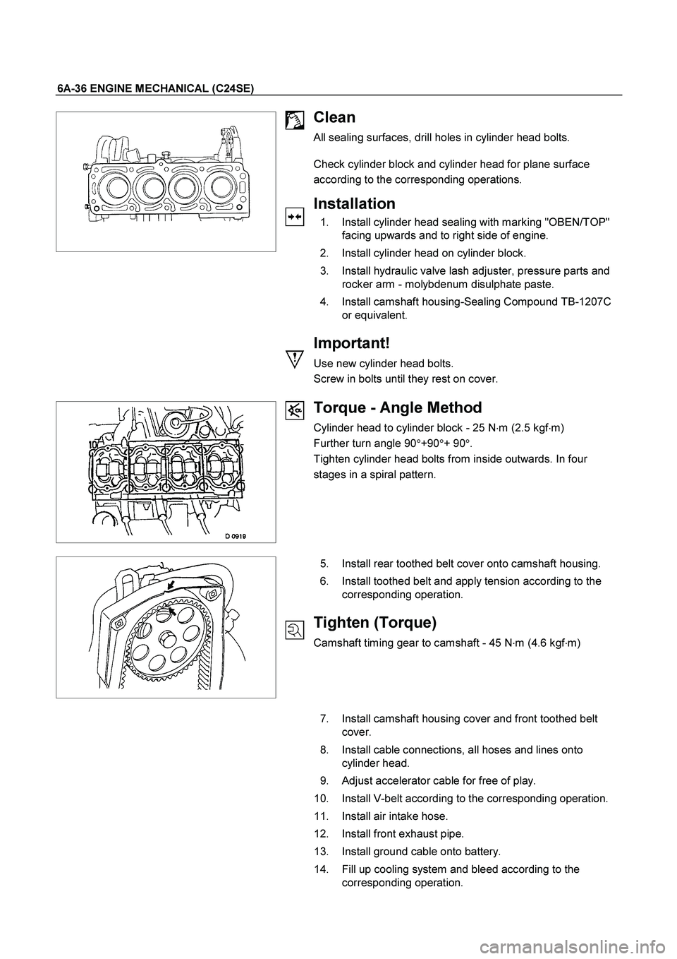
Installation
1. Install cylinder head sealing with marking "OBEN/TOP"
facing upwards and to right side of engine.
2. Install cylinder head on cylinder block.
3. Install hydraulic valve lash adjuster, pressure parts and
rocker arm - molybdenum disulphate paste.
4. Install camshaft housing-Sealing Compound TB-1207C
or equivalent.
Important!
Use new cylinder head bolts.
Screw in bolts until they rest on cover.
Torque - Angle Method
Cylinder head to cylinder block - 25 N�
m (2.5 kgf�
m)
Further turn angle 90�
+90�
+ 90�
.
Tighten cylinder head bolts from inside outwards. In four
stages in a spiral pattern.
5. Install rear toothed belt cover onto camshaft housing.
6. Install toothed belt and apply tension according to the
corresponding operation.
Tighten (Torque)
Camshaft timing gear to camshaft - 45 N�
m (4.6 kgf�
m)
7. Install camshaft housing cover and front toothed belt
cover.
8. Install cable connections, all hoses and lines onto
cylinder head.
9. Adjust accelerator cable for free of play.
10. Install V-belt according to the corresponding operation.
11. Install air intake hose.
12. Install front exhaust pipe.
13. Install ground cable onto battery.
14. Fill up cooling system and bleed according to the
corresponding operation.