Page 3303 of 4264
IMMOBILIZER SYSTEM 11A-17
Important Instructions
Only data corresponding to the delivery status of the
vehicle can be issued. Car pass data requests will onl
y
be processed if the first column is filled out completely.
Signed and sent to your organization along with proof of
ownership.
Information via telephone is only possible in exceptional
circumstances via your service organization.
As for the delivery of new vehicles, the customer must
be informed about all features of the car pass that are
relevant to vehicle security, for example, that the ca
r
pass should be kept in a safe place(not in the vehicle)
and should be presented when an authorized you
r
organization name workshop is visited, The exact
phrasing can be found in the relevant Owner's Manual.
Page 3318 of 4264
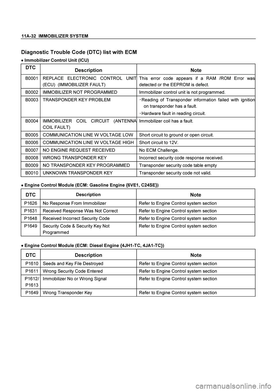
11A-32 IMMOBILIZER SYSTEM
Diagnostic Trouble Code (DTC) list with ECM
�
�� � Immobilizer Control Unit (ICU)
DTC
Description Note
B0001
REPLACE ELECTRONIC CONTROL UNIT
(ECU) (IMMOBILIZER FAULT) This error code appears if a RAM /ROM Error was
detected or the EEPROM is defect.
B0002 IMMOBILIZER NOT PROGRAMMED Immobilizer control unit is not programmed.
B0003 TRANSPONDER KEY PROBLEM �
Reading of Transponder information failed with ignition
on transponder has a fault.
�
Hardware fault in reading circuit.
B0004
IMMOBILIZER COIL CIRCUIT (ANTENNA
COIL FAULT) Immobilizer coil has a fault.
B0005 COMMUNICATION LINE W VOLTAGE LOW Short circuit to ground or open circuit.
B0006 COMMUNICATION LINE W VOLTAGE HIGH Short circuit to 12V.
B0007 NO ENGINE REQUEST RECEIVED No ECM Challenge.
B0008 WRONG TRANSPONDER KEY Incorrect security code response received.
B0009 NO TRANSPONDER KEY PROGRAMMED Transponder security code table empty
B0010 UNKNOWN TRANSPONDER KEY Transponder security code not valid.
�
�� � Engine Control Module (ECM: Gasoline Engine {6VE1, C24SE})
DTC Description
Note
P1626 No Response From Immobilizer Refer to Engine Control system section
P1631 Received Response Was Not Correct Refer to Engine Control system section
P1648 Received Incorrect Security Code Refer to Engine Control system section
P1649 Security Code & Security Key Not
Programmed Refer to Engine Control system section
�
�� � Engine Control Module (ECM: Diesel Engine {4JH1-TC, 4JA1-TC})
DTC Description Note
P1610 Seeds and Key File Destroyed Refer to Engine Control system section
P1611 Wrong Security Code Entered Refer to Engine Control system section
P1612/
P1613 Immobilizer No or Wrong Signal Refer to Engine Control system section
P1649 Wrong Transponder Key Refer to Engine Control system section
Page 3319 of 4264
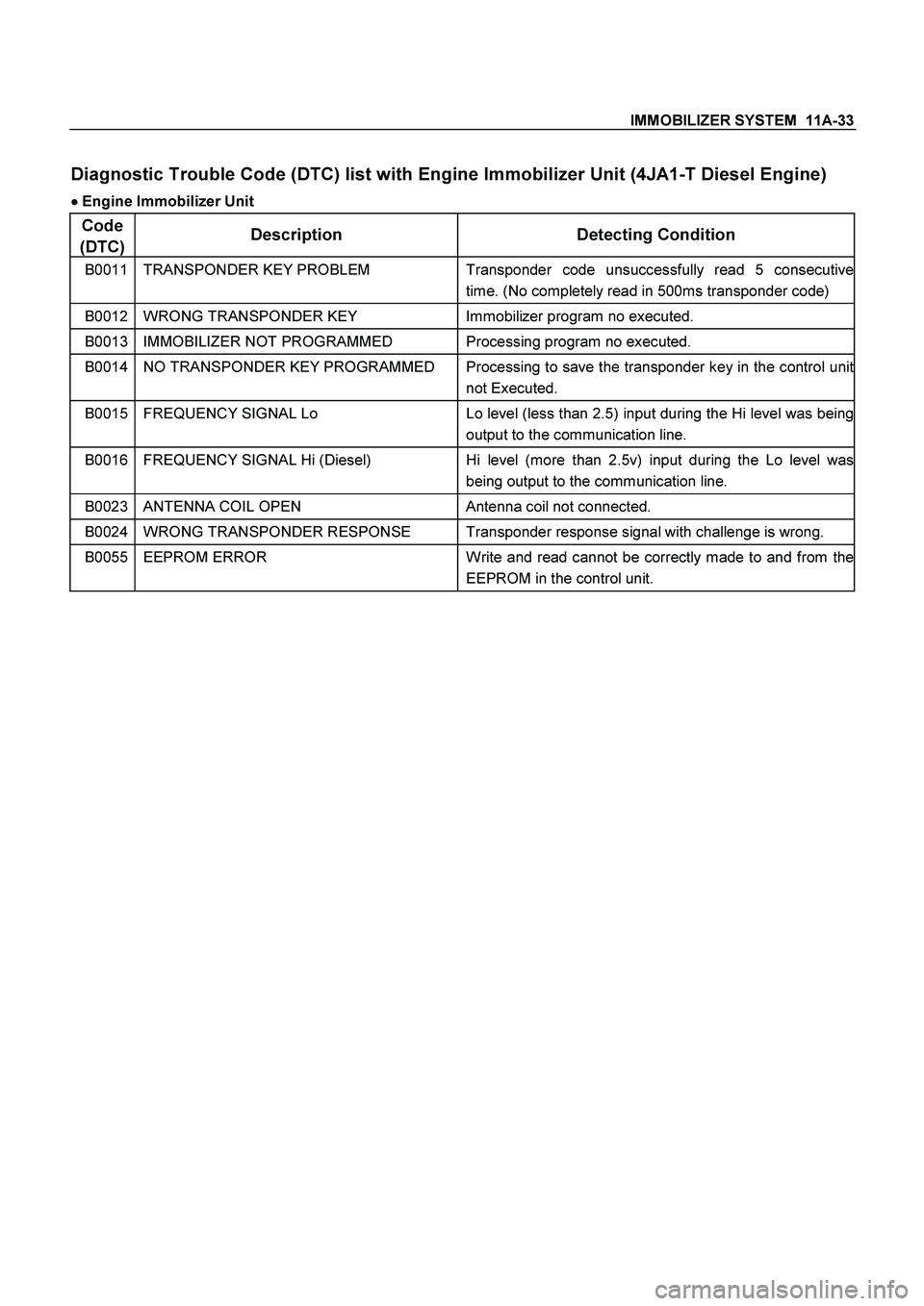
IMMOBILIZER SYSTEM 11A-33
Diagnostic Trouble Code (DTC) list with Engine Immobilizer Unit (4JA1-T Diesel Engine)
�
�� � Engine Immobilizer Unit
Code
(DTC) Description Detecting Condition
B0011 TRANSPONDER KEY PROBLEM Transponder code unsuccessfully read 5 consecutive
time. (No completely read in 500ms transponder code)
B0012 WRONG TRANSPONDER KEY Immobilizer program no executed.
B0013 IMMOBILIZER NOT PROGRAMMED Processing program no executed.
B0014 NO TRANSPONDER KEY PROGRAMMED Processing to save the transponder key in the control unit
not Executed.
B0015 FREQUENCY SIGNAL Lo Lo level (less than 2.5) input during the Hi level was being
output to the communication line.
B0016 FREQUENCY SIGNAL Hi (Diesel) Hi level (more than 2.5v) input during the Lo level was
being output to the communication line.
B0023 ANTENNA COIL OPEN Antenna coil not connected.
B0024 WRONG TRANSPONDER RESPONSE Transponder response signal with challenge is wrong.
B0055 EEPROM ERROR Write and read cannot be correctly made to and from the
EEPROM in the control unit.
Page 3527 of 4264
FRONT SUSPENSION 3C-35
3. Apply the setting marks(2) to the height control
arm and torsion bar, then remove height control
arm.
NOTE: “Besco chassis grease” shall be applied on
contact area of height control arm with frame.
(RH & LH Both side)
410RS005
4. Apply the setting marks (3) to the torsion bar and
lower control arm, then remove torsion bar.
RTW340SH000301
Inspection and Repair
Make necessary correction or parts replacement if
wear, damage, corrosion or any other abnormal
condition are found through inspection.
Check the following parts:
� Torsion bar
�
Height control arm
�
Adjust bolt
Installation
1. Apply grease to the serrated portions, then install
torsion bar. Make sure the bars are on their correct
respective sides and align the setting marks (3).
410RS007
RTW340SH000301
Page 3668 of 4264
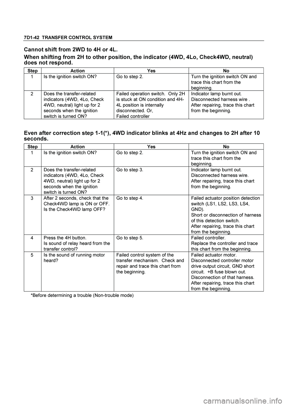
7D1-42 TRANSFER CONTROL SYSTEM
Cannot shift from 2WD to 4H or 4L.
When shifting from 2H to other position, the indicator (4WD, 4Lo, Check4WD, neutral)
does not respond.
Step Action Yes No
1 Is the ignition switch ON? Go to step 2. Turn the ignition switch ON and
trace this chart from the
beginning.
2 Does the transfer-related
indicators (4WD, 4Lo, Check
4WD, neutral) light up for 2
seconds when the ignition
switch is turned ON? Failed operation switch. Only 2H
is stuck at ON condition and 4H-
4L position is internally
disconnected. Or,
Failed controller Indicator lamp burnt out.
Disconnected harness wire .
After repairing, trace this chart
from the beginning.
Even after correction step 1-1(*), 4WD indicator blinks at 4Hz and changes to 2H after 10
seconds.
Step Action Yes No
1 Is the ignition switch ON? Go to step 2. Turn the ignition switch ON and
trace this chart from the
beginning.
2 Does the transfer-related
indicators (4WD, 4Lo, Check
4WD, neutral) light up for 2
seconds when the ignition
switch is turned ON? Go to step 3. Indicator lamp burnt out.
Disconnected harness wire.
After repairing, trace this chart
from the beginning.
3 After 2 seconds, check that the
Check4WD lamp is ON or OFF.
Is the Check4WD lamp OFF? Go to step 4. Failed actuator position detection
switch (LS1, LS2, LS3, LS4,
GND).
Short or disconnection of harness
of this detection switch.
After repairing, trace this chart
from the beginning.
4 Press the 4H button.
Is sound of relay heard from the
transfer control? Go to step 5. Failed controller.
Replace the controller and trace
this chart from the beginning.
5 Is the sound of running motor
heard? Failed control system of the
transfer mechanism. Check and
repair and trace this chart from
the beginning. Failed actuator motor.
Disconnected controller motor
drive output circuit, GND short
circuit. +B fuse blown out.
Disconnection of that harness.
After repairing, trace this chart
from the beginning.
*Before determining a trouble (Non-trouble mode)
Page 3671 of 4264
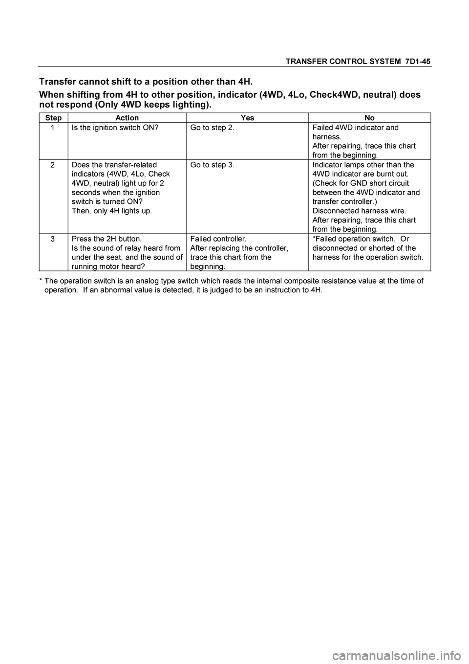
TRANSFER CONTROL SYSTEM 7D1-45
Transfer cannot shift to a position other than 4H.
When shifting from 4H to other position, indicator (4WD, 4Lo, Check4WD, neutral) does
not respond (Only 4WD keeps lighting).
Step Action Yes No
1 Is the ignition switch ON? Go to step 2. Failed 4WD indicator and
harness.
After repairing, trace this chart
from the beginning.
2 Does the transfer-related
indicators (4WD, 4Lo, Check
4WD, neutral) light up for 2
seconds when the ignition
switch is turned ON?
Then, only 4H lights up. Go to step 3. Indicator lamps other than the
4WD indicator are burnt out.
(Check for GND short circuit
between the 4WD indicator and
transfer controller.)
Disconnected harness wire.
After repairing, trace this chart
from the beginning.
3 Press the 2H button.
Is the sound of relay heard from
under the seat, and the sound of
running motor heard? Failed controller.
After replacing the controller,
trace this chart from the
beginning. *Failed operation switch. Or
disconnected or shorted of the
harness for the operation switch.
* The operation switch is an analog type switch which reads the internal composite resistance value at the time of
operation. If an abnormal value is detected, it is judged to be an instruction to 4H.
Page 3673 of 4264
TRANSFER CONTROL SYSTEM 7D1-47
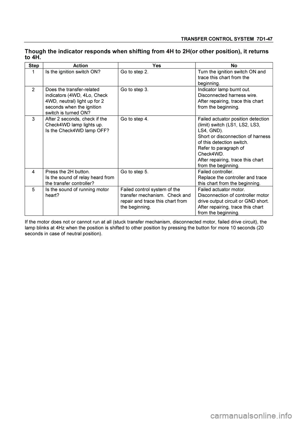
Though the indicator responds when shifting from 4H to 2H(or other position), it returns
to 4H.
Step Action Yes No
1 Is the ignition switch ON? Go to step 2. Turn the ignition switch ON and
trace this chart from the
beginning.
2 Does the transfer-related
indicators (4WD, 4Lo, Check
4WD, neutral) light up for 2
seconds when the ignition
switch is turned ON? Go to step 3. Indicator lamp burnt out.
Disconnected harness wire.
After repairing, trace this chart
from the beginning.
3 After 2 seconds, check if the
Check4WD lamp lights up.
Is the Check4WD lamp OFF? Go to step 4. Failed actuator position detection
(limit) switch (LS1, LS2, LS3,
LS4, GND).
Short or disconnection of harness
of this detection switch.
Refer to paragraph of
Check4WD.
After repairing, trace this chart
from the beginning.
4 Press the 2H button.
Is the sound of relay heard from
the transfer controller? Go to step 5. Failed controller.
Replace the controller and trace
this chart from the beginning.
5 Is the sound of running motor
heart? Failed control system of the
transfer mechanism. Check and
repair and trace this chart from
the beginning. Failed actuator motor.
Disconnection of controller motor
drive output circuit or GND short.
After repairing, trace this chart
from the beginning.
If the motor does not or cannot run at all (stuck transfer mechanism, disconnected motor, failed drive circuit), the
lamp blinks at 4Hz when the position is shifted to other position by pressing the button for more 10 seconds (20
seconds in case of neutral position).
Page 3704 of 4264
7A2-24 TRANSMISSION CONTROL SYSTEM (AW30 –40LE) (V6 3.5L)
After recording the snapshot in Tech2, transfer the data
from Tech2 to PC by the below procedures.
1.
Start TIS2000.
2.
Select [Snapshot Upload] on the TIS2000 start
screen.
3.
Select [Upload from trouble diagnosis tool
(transfer from diagnosis tester)] or click the
corresponding icon of the tool bar.
4.
Select Tech2, and transfer the recorded snapshot
information.
5.
Select the transferred snapshot.
6.
After ending transfer of the snapshot, data
parameter list is displayed on the screen.
3. Snapshot data is displayed with TIS2000
[Snapshot Upload] function.
Snapshot is stored in the PC hard disk or floppy disk,
and can be displayed any time.
Stored snapshot can be displayed by the below
procedures.
1.
Start TIS2000.
2.
Select [Snapshot Upload] on the TIS2000 start
screen.
3.
Select [Open the existing files] or click the
corresponding icon of the tool bar.
4.
Select the transferred snapshot.
5.
Open the snapshot, to display the data paramete
r
list on the screen.