Page 264 of 4449

BRAKE SIGNAL CIRCUIT
AT-187
D
E
F
G
H
I
J
K
L
MA
B
AT
Revision: 2004 November 2004 FX35/FX45
BRAKE SIGNAL CIRCUITPFP:25320
CONSULT-II Reference ValueACS007GA
Diagnostic ProcedureACS007GB
1. CHECK CAN COMMUNICATION LINE
Perform the self-diagnosis. Refer to AT- 9 4 , "
SELF-DIAGNOSTIC RESULT MODE" , AT- 1 0 3 , "TCM SELF-
DIAGNOSTIC PROCEDURE (NO TOOLS)" .
Is a malfunction in the CAN communication indicated in the results?
YES >> Check CAN communication line. Refer to AT- 1 0 5 , "DTC U1000 CAN COMMUNICATION LINE" .
NO >> GO TO 2.
2. CHECK STOP LAMP SWITCH CIRCUIT
With CONSULT-II
1. Turn ignition switch “ON”. (Do not start engine.)
2. Select “ECU INPUT SIGNALS” in “DATA MONITOR” mode for
“A/T” with CONSULT-II.
3. Read out ON/OFF switching action of the “BRAKE SW”.
OK or NG
OK >>INSPECTION END
NG >> GO TO 3.
3. CHECK STOP LAMP SWITCH
Check continuity between stop lamp switch harness connector E210
terminals 1 and 2. Refer to AT- 1 8 8 , "
Wiring Diagram — AT — NON-
DTC" .
Check stop lamp switch after adjusting brake pedal — refer to
BR-6, "
Inspection and Adjustment" .
OK or NG
OK >> Check the following items. If NG, repair or replace dam-
aged parts.
�Harness for short or open between battery and stop lamp switch.
�Harness for short or open between stop lamp switch and unified meter and A/C amp.
NG >> Repair or replace the stop lamp switch.
Item name Condition Display value
BRAKE SWDepressed brake pedal. ON
Released brake pedal. OFF
Item name Condition Display value
BRAKE SWDepressed brake pedal. ON
Released brake pedal. OFF
PCIA0070E
Condition Continuity
When brake pedal is depressed Yes
When brake pedal is released No
SCIA2144E
Page 316 of 4449
KEY INTERLOCK CABLE
AT-239
D
E
F
G
H
I
J
K
L
MA
B
AT
Revision: 2004 November 2004 FX35/FX45
KEY INTERLOCK CABLEPFP:34908
ComponentsACS002RX
CAUTION:
�Install key interlock cable in such a way that it will not be damaged by sharp bends, twists or inter-
ference with adjacent parts.
�After installing key interlock cable to control device, make sure that casing cap and bracket are
firmly secured in their positions. If casing cap be removed with an external load of less than 39.2 N
(4.0 kg, 8.8 lb), replace key interlock cable with new one.
SCIA2150E
Page 323 of 4449

AT-246
ON-VEHICLE SERVICE
Revision: 2004 November 2004 FX35/FX45
Installation
CAUTION:
After completing installation, check A/T fluid leakage and fluid level. Refer to AT- 1 2 , "
Changing A/T
Fluid" , AT- 1 2 , "Checking A/T Fluid" .
1. Install O-ring in A/T assembly harness connector.
CAUTION:
�Do not reuse O-ring.
�Apply ATF to O-ring.
2. Install A/T fluid temperature sensor 2 to bracket.
3. Install A/T fluid temperature sensor 2 in control valve with TCM.
(With bracket.)
CAUTION:
Adjust bolt hole of bracket to bolt hole of control valve with
TCM.
4. Install control valve with TCM in transmission case.
CAUTION:
�Make sure that turbine revolution sensor securely installs
turbine revolution sensor hole.
�Hang down revolution sensor harness toward outside so
as not to disturb installation of control valve with TCM.
�Adjust A/T assembly harness connector of control valve
with TCM to terminal hole of transmission case.
SCIA5155E
SCIA5264E
: 7.9 N·m (0.81 kg-m, 70 in-lb)
SCIA5301E
SCIA5034E
Page 324 of 4449
ON-VEHICLE SERVICE
AT-247
D
E
F
G
H
I
J
K
L
MA
B
AT
Revision: 2004 November 2004 FX35/FX45
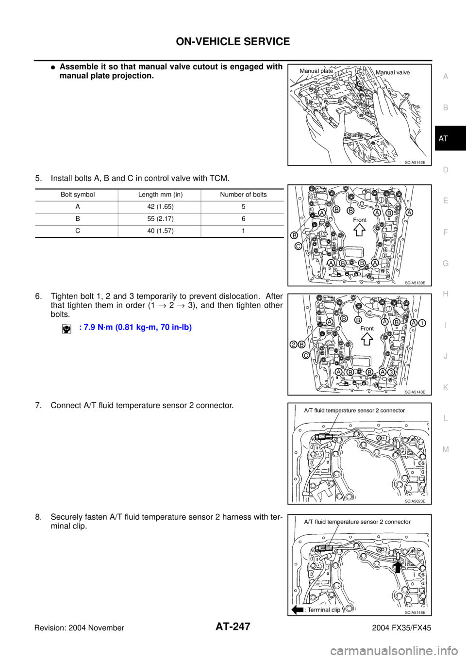
�Assemble it so that manual valve cutout is engaged with
manual plate projection.
5. Install bolts A, B and C in control valve with TCM.
6. Tighten bolt 1, 2 and 3 temporarily to prevent dislocation. After
that tighten them in order (1 → 2 → 3), and then tighten other
bolts.
7. Connect A/T fluid temperature sensor 2 connector.
8. Securely fasten A/T fluid temperature sensor 2 harness with ter-
minal clip.
SCIA5142E
Bolt symbol Length mm (in) Number of bolts
A 42 (1.65) 5
B 55 (2.17) 6
C 40 (1.57) 1
SCIA5139E
: 7.9 N·m (0.81 kg-m, 70 in-lb)
SCIA5140E
SCIA5023E
SCIA5146E
Page 325 of 4449
AT-248
ON-VEHICLE SERVICE
Revision: 2004 November 2004 FX35/FX45
9. Connect revolution sensor connector.
10. Securely fasten revolution sensor harness with terminal clips.
11. Install magnets in oil pan.
12. Install oil pan to transmission case.
a. Install oil pan gasket to oil pan.
CAUTION:
�Do not reuse oil pan gasket.
�Install it in the direction to align hole positions.
�Complete remove all moisture, oil and old gasket, etc. from oil pan gasket mounting surface.
b. Install oil pan (with oil pan gasket) to transmission case.
CAUTION:
�Install it so that drain plug comes to the position as
shown in the figure.
�Be careful not to pinch harnesses.
�Complete remove all moisture, oil and old gasket, etc.
from oil pan mounting surface.
SCIA5024E
SCIA3969E
SCIA5200E
SCIA2308E
Page 328 of 4449
ON-VEHICLE SERVICE
AT-251
D
E
F
G
H
I
J
K
L
MA
B
AT
Revision: 2004 November 2004 FX35/FX45
Installation
CAUTION:
After completing installation, check A/T fluid leakage and fluid level. Refer to AT- 1 2 , "
Changing A/T
Fluid" , AT- 1 2 , "Checking A/T Fluid" .
1. Install A/T fluid temperature sensor 2 to bracket.
2. Install A/T fluid temperature sensor 2 in control valve with TCM.
(With bracket.)
3. Connect A/T fluid temperature sensor 2 connector.
4. Securely fasten A/T fluid temperature sensor 2 harness with ter-
minal clip.
5. Install oil pan to transmission case.
a. Install oil pan gasket to oil pan.
CAUTION:
�Do not reuse oil pan gasket.
�Install it in the direction to align hole positions.
�Complete remove all moisture, oil and old gasket, etc. from oil pan mounting surface.
SCIA5264E
: 7.9 N·m (0.81 kg-m, 70 in-lb)
SCIA5302E
SCIA5023E
SCIA5146E
Page 339 of 4449

AT-262
ON-VEHICLE SERVICE
Revision: 2004 November 2004 FX35/FX45
INSTALLATION
CAUTION:
After completing installation, check A/T fluid leakage and fluid level. Refer to AT- 1 2 , "
Changing A/T
Fluid" , AT- 1 2 , "Checking A/T Fluid" .
1. Install revolution sensor in transmission case.
CAUTION:
�Do not subject it to impact by dropping or hitting it.
�Do not disassemble.
�Do not allow metal filings, etc. to get on the sensor's front
edge magnetic area.
�Do not place in an area affected by magnetism.
2. Connect revolution sensor connector.
3. Securely fasten revolution sensor harness with clips.
4. Apply recommended sealant (Genuine Anaerobic Liquid Gasket
or equivalent. Refer to GI-48, "
Recommended Chemical Prod-
ucts and Sealants" .) to rear extension assembly as shown in
the figure.
CAUTION:
Completely remove all moisture, oil and old sealant, etc.
from transmission case and rear extension assembly
mounting surfaces.
5. Install rear extension assembly to transmission case. (With nee-
dle bearing.): 5.8 N·m (0.59 kg-m, 51 in-lb)
SCIA3997E
SCIA3969E
SCIA5212E
SCIA3431E
Page 344 of 4449
 from A/T assembly.
CAUTION:
�Do not subject it to impact by dr")
TRANSMISSION ASSEMBLY
AT-267
D
E
F
G
H
I
J
K
L
MA
B
AT
Revision: 2004 November 2004 FX35/FX45
10. Remove crankshaft position sensor (POS) from A/T assembly.
CAUTION:
�Do not subject it to impact by dropping or hitting it.
�Do not disassemble.
�Do not allow metal filings, etc. to get on the sensor's front
edge magnetic area.
�Do not place in an area affected by magnetism.
11. Remove starter motor. Refer to SC-18, "
VQ35DE ENGINE
MODELS (2WD)" .
12. Remove fluid cooler tube.
13. Remove rear plate from converter housing part. Refer to EM-30,
"Removal and Installation" .
14. Remove rear cover plate. Refer to EM-30, "
Removal and Installation" .
15. Turn crankshaft, and remove the four tightening bolts for drive
plate and torque converter.
CAUTION:
When turning crankshaft, turn it clockwise as viewed from
the front of the engine.
16. Support transmission assembly with a transmission jack.
CAUTION:
When setting the transmission jack, be careful not to allow
it to collide against the drain plug.
17. Remove engine rear member with power tool.
18. Remove air breather hose. Refer to AT- 2 6 4 , "
Removal and
Installation" .
19. Disconnect A/T assembly harness connector.
20. Remove A/T fluid charging pipe from transmission assembly.
21. Plug up openings such as the A/T fluid charging pipe hole, etc.
22. Remove bolts fixing transmission assembly to engine with power tool.
23. Remove transmission assembly from vehicle with a transmis-
sion jack.
�Secure torque converter to prevent it from dropping.
�Secure transmission assembly to a jack.
INSPECTION
Installation and Inspection of Torque Converter
�After inserting a torque converter to a transmission, be sure to
check distance “A” to ensure it is within the reference value limit.
SCIA2155E
SCIA2288E
SCIA0499E
Distance “A”: 25.0 mm (0.98 in) or more
SAT017B