Page 982 of 4449

BACK DOOR AUTO CLOSURE SYSTEM
BL-175
C
D
E
F
G
H
J
K
L
MA
B
BL
Revision: 2004 November 2004 FX35/FX45
3. CHECK GROUND CIRCUIT
Check continuity between back door closure motor connector D109
terminal 8 and ground.
OK or NG
OK >> GO TO 4.
NG >> Repair or replace harness.
4. CHECK BACK DOOR CLOSURE CONTROL UNIT OUTPUT SIGNAL
1. Connect back door closure control unit connector.
2. Check voltage between back door closure control unit connector
D106 terminal 9 and ground.
OK or NG
OK >> Replace back door lock assembly.
NG >> Replace back door closure control unit.
Back Door Opener Switch Check (With Intelligent Key)AIS004U8
1. CHECK BACK DOOR OPENER SWITCH SIGNAL
1. Turn ignition switch OFF.
2. Check voltage between back door closure control unit connector and ground.
OK or NG
OK >> Back door opener switch is OK.
NG >> GO TO 2.8 (B) – Ground : Continuity should exist.
PIIA6170E
Back door is closed
9 (P) – Ground : Battery voltage
PIIA6177E
ConnectorTerminals (Wire color)
ConditionVoltage (V)
(Approx.)
(+) (-)
D106 6 (LG) GroundBack door opener switch
: ON0
Back door opener switch
: OFF5
PIIA6178E
Page 983 of 4449

BL-176
BACK DOOR AUTO CLOSURE SYSTEM
Revision: 2004 November 2004 FX35/FX45
2. CHECK HARNESS 1
1. Disconnect Intelligent Key unit and back door closure control unit connector.
2. Check continuity between Intelligent Key unit connector M34 ter-
minal 23 and back door closure control unit connector D106 ter-
minal 6.
3. Check continuity between Intelligent Key unit connector M34 ter-
minal 23 and ground.
OK or NG
OK >> GO TO 3.
NG >> Replace or repair malfunction harness.
3. CHECK HARNESS 2
1. Disconnect Intelligent Key unit and back door opener switch connector.
2. Check continuity between Intelligent Key unit connector M34 ter-
minal 24 and back door opener switch connector D112 terminal
1.
3. Check continuity between Intelligent Key unit connector M34 ter-
minal 24 and ground.
OK or NG
OK >> GO TO 4.
NG >> Replace or repair malfunction harness.
4. CHECK BACK DOOR OPENER SWITCH GROUND CIRCUIT
Check continuity between back door opener switch connector D112
terminal 2 and ground.
OK or NG
OK >> GO TO 5.
NG >> Repair or replace harness.
5. CHECK BACK DOOR OPENER SWITCH
Check continuity between back door opener switch terminals 1 and
2.
OK or NG
OK >> GO TO 6.
NG >> Replace back door opener switch.23 (L/Y) – 6 (LG) : Continuity should exist.
23 (L/Y) - Ground : Continuity should not exist.
PIIB0216E
24 (P) – 1 (Y) : Continuity should exist.
24 (P) - Ground : Continuity should not exist.
PIIB0217E
2 (B) – Ground : Continuity should exist.
PIIA6180E
Terminals Condition Continuity
12Back door opener switch: ON Yes
Back door opener switch: OFF No
PIIA6181E
Page 984 of 4449

BACK DOOR AUTO CLOSURE SYSTEM
BL-177
C
D
E
F
G
H
J
K
L
MA
B
BL
Revision: 2004 November 2004 FX35/FX45
6. CHECK BACK DOOR CLOSURE CONTROL UNIT OUTPUT SIGNAL
1. Connect back door closure control unit connector.
2. Check voltage between back door closure control unit connector
D106 terminal 6 and ground.
OK or NG
OK >> Replace Intelligent Key unit.
NG >> Replace back door closure control unit.
Back Door Opener Switch Check (Without Intelligent Key)AIS004U9
1. CHECK BACK DOOR OPENER SWITCH SIGNAL
1. Turn ignition switch OFF.
2. Check voltage between back door closure control unit connector and ground.
OK or NG
OK >> Back door opener switch is OK.
NG >> GO TO 2.
2. CHECK HARNESS CONTINUITY
1. Disconnect back door closure control unit and back door opener switch connector.
2. Check continuity between back door closure control unit con-
nector D106 terminal 6 and back door opener switch connector
D112 terminal 1.
OK or NG
OK >> GO TO 3.
NG >> Repair or replace harness between back door closure
control unit and back door opener switch. 6 (LG) – Ground : Approx. 5V
PIIA6178E
ConnectorTerminals (Wire color)
ConditionVoltage (V)
(Approx.)
(+) (-)
D106 6 (Y) GroundBack door opener switch
: ON0
Back door opener switch
: OFF5
PIIA6178E
6 (Y) – 1 (Y) : Continuity should exist.
PIIA6179E
Page 985 of 4449
BL-178
BACK DOOR AUTO CLOSURE SYSTEM
Revision: 2004 November 2004 FX35/FX45
3. CHECK GROUND CIRCUIT
Check continuity between back door opener switch connector D112
terminal 2 and ground.
OK or NG
OK >> GO TO 4.
NG >> Repair or replace harness.
4. CHECK BACK DOOR OPENER SWITCH
Check continuity between back door opener switch terminals 1 and
2.
OK or NG
OK >> GO TO 5.
NG >> Replace back door opener switch.
5. CHECK BACK DOOR CLOSURE CONTROL UNIT OUTPUT SIGNAL
1. Connect back door closure control unit connector.
2. Check voltage between back door closure control unit connector
D106 terminal 6 and ground.
OK or NG
OK >> Check condition of harness and connector.
NG >> Replace back door closure control unit.2 (B) – Ground : Continuity should exist.
PIIA6180E
Terminals Condition Continuity
12Back door opener switch: ON Yes
Back door opener switch: OFF No
PIIA6181E
6 (Y) – Ground : Approx. 5V
PIIA6178E
Page 986 of 4449

BACK DOOR AUTO CLOSURE SYSTEM
BL-179
C
D
E
F
G
H
J
K
L
MA
B
BL
Revision: 2004 November 2004 FX35/FX45
Unlock Sensor Check (Without Intelligent Key)AIS004UA
1. CHECK UNLOCK SENSOR SIGNAL
1. Turn ignition switch OFF.
2. Check voltage between back door closure control unit connector
and ground.
OK or NG
OK >> Unlock sensor is OK.
NG >> GO TO 2.
2. CHECK HARNESS CONTINUITY
1. Disconnect back door closure control unit and front door lock assembly (passenger side) connector.
2. Check continuity between back door closure control unit con-
nector D106 terminal 5 and front door lock assembly (passenger
side) connector D40 terminal 5.
OK or NG
OK >> GO TO 3.
NG >> Repair or replace harness between back door closure
control unit and front door lock assembly (passenger
side).
3. CHECK GROUND CIRCUIT
Check continuity between front door lock assembly (passenger side)
connector D40 terminal 4 and ground.
OK or NG
OK >> GO TO 4.
NG >> Repair or replace harness.
ConnectorTerminals (Wire color)
ConditionVoltage (V)
(Approx.)
(+) (-)
D106 5 (W) GroundPassenger side door lock is
locked5
Passenger side door lock is
unlocked0
PIIA6182E
5 (W) – 5 (W) : Continuity should exist.
PIIA6183E
4 (B) – Ground : Continuity should exist.
PIIA6184E
Page 987 of 4449

BL-180
BACK DOOR AUTO CLOSURE SYSTEM
Revision: 2004 November 2004 FX35/FX45
4. CHECK BACK DOOR CLOSURE CONTROL UNIT OUTPUT SIGNAL
1. Connect back door closure control unit connector.
2. Check voltage between back door closure control unit connector
D106 terminal 5 and ground.
OK or NG
OK >> Replace front door lock assembly (passenger side).
NG >> Replace back door closure control unit.
Closure Motor CheckAIS004UB
1. CHECK BACK DOOR CLOSURE MOTOR
1. Turn ignition switch OFF.
2. Check the signal between back door closure control unit connector and ground with oscilloscope.
OK or NG
OK >> GO TO 2.
NG >> Replace back door closure control unit.
2. CHECK HARNESS CONTINUITY
1. Disconnect back door closure control unit and back door closure motor connector.
2. Check continuity between back door closure control unit con-
nector D106 terminals 2, 3 and back door closure motor connec-
tor D109 terminals 1, 2.
3. Check continuity between back door closure control unit con-
nector D106 terminals 2, 3 and ground.
OK or NG
OK >> Replace back door closure motor.
NG >> Repair or replace harness.
Removal and Installation of Back Door Closer Control UnitAIS004UC
1. Remove the back door finisher.EI-46, "Removal and Installation" .
2. Disconnect the back door closer control unit harness, remove the screw and back door closer control unit.5 (W) – Ground : Approx. 5V
PIIA6182E
Con-
nectorTerminals (Wire color)
Back door
conditionSignal
(Reference value)
(+) (-)
D1062 (PU)
GroundFully closed
→ fully open
3 (G)Fully open →
fully closed
PIIA6185E
SIIA1480J
2 (PU) – 1 (PU) : Continuity should exist.
3 (G) – 2 (G) : Continuity should exist.
2 (PU) – Ground : Continuity should not exist.
3 (G) – Ground : Continuity should not exist.
PIIA6186E
Page 1006 of 4449

VEHICLE SECURITY (THEFT WARNING) SYSTEM
BL-199
C
D
E
F
G
H
J
K
L
MA
B
BL
Revision: 2004 November 2004 FX35/FX45
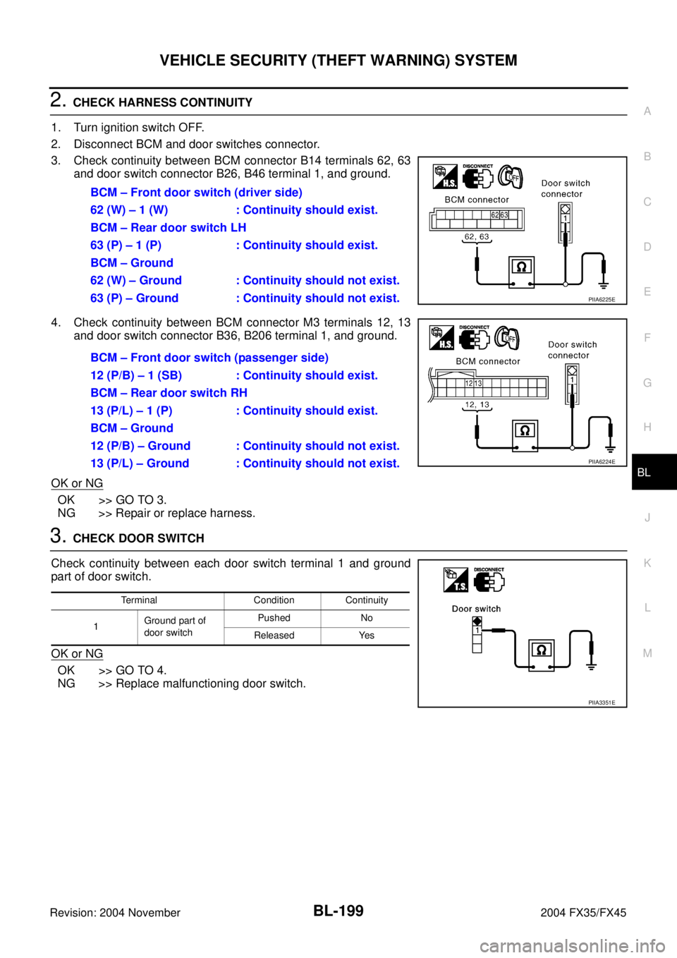
2. CHECK HARNESS CONTINUITY
1. Turn ignition switch OFF.
2. Disconnect BCM and door switches connector.
3. Check continuity between BCM connector B14 terminals 62, 63
and door switch connector B26, B46 terminal 1, and ground.
4. Check continuity between BCM connector M3 terminals 12, 13
and door switch connector B36, B206 terminal 1, and ground.
OK or NG
OK >> GO TO 3.
NG >> Repair or replace harness.
3. CHECK DOOR SWITCH
Check continuity between each door switch terminal 1 and ground
part of door switch.
OK or NG
OK >> GO TO 4.
NG >> Replace malfunctioning door switch.BCM – Front door switch (driver side)
62 (W) – 1 (W) : Continuity should exist.
BCM – Rear door switch LH
63 (P) – 1 (P) : Continuity should exist.
BCM – Ground
62 (W) – Ground : Continuity should not exist.
63 (P) – Ground : Continuity should not exist.
PIIA6225E
BCM – Front door switch (passenger side)
12 (P/B) – 1 (SB) : Continuity should exist.
BCM – Rear door switch RH
13 (P/L) – 1 (P) : Continuity should exist.
BCM – Ground
12 (P/B) – Ground : Continuity should not exist.
13 (P/L) – Ground : Continuity should not exist.
PIIA6224E
Terminal Condition Continuity
1Ground part of
door switchPushed No
Released Yes
PIIA3351E
Page 1009 of 4449

BL-202
VEHICLE SECURITY (THEFT WARNING) SYSTEM
Revision: 2004 November 2004 FX35/FX45
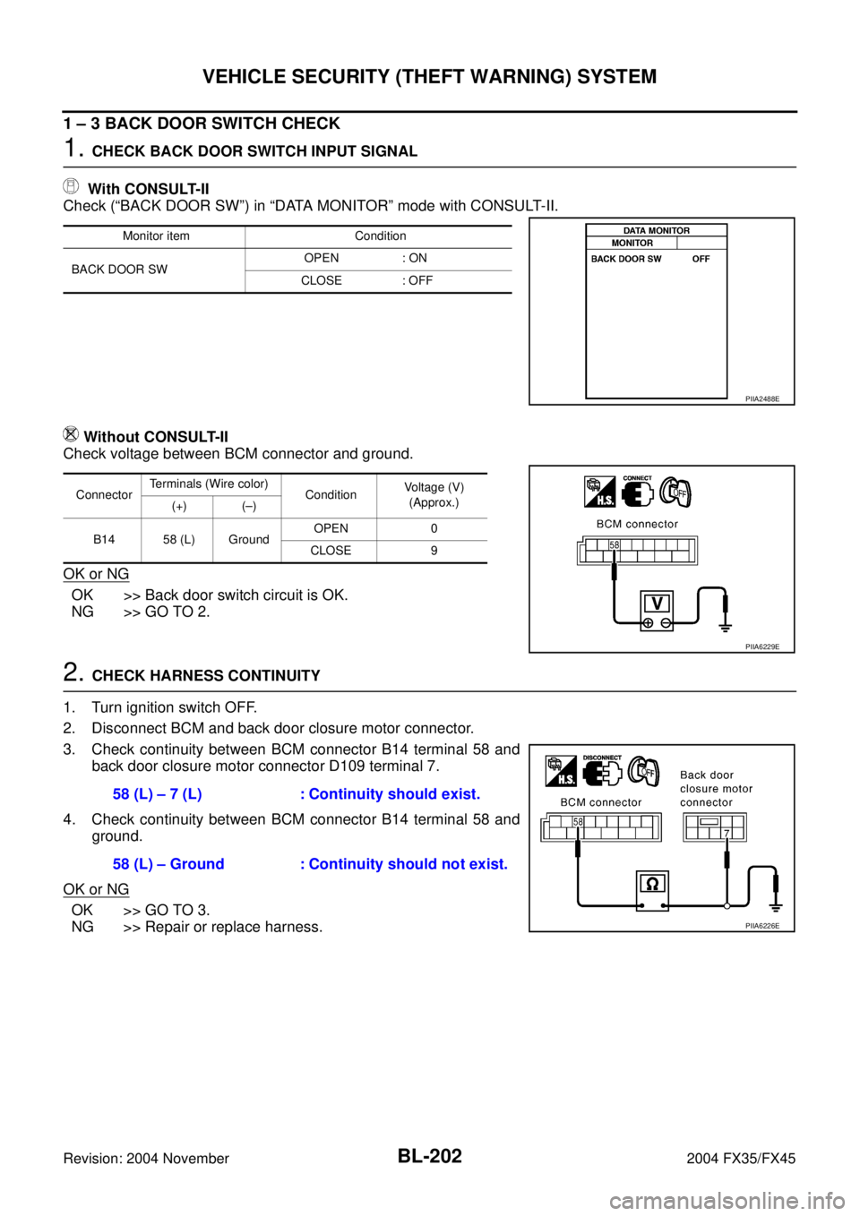
1 – 3 BACK DOOR SWITCH CHECK
1. CHECK BACK DOOR SWITCH INPUT SIGNAL
With CONSULT-II
Check (“BACK DOOR SW”) in “DATA MONITOR” mode with CONSULT-II.
Without CONSULT-II
Check voltage between BCM connector and ground.
OK or NG
OK >> Back door switch circuit is OK.
NG >> GO TO 2.
2. CHECK HARNESS CONTINUITY
1. Turn ignition switch OFF.
2. Disconnect BCM and back door closure motor connector.
3. Check continuity between BCM connector B14 terminal 58 and
back door closure motor connector D109 terminal 7.
4. Check continuity between BCM connector B14 terminal 58 and
ground.
OK or NG
OK >> GO TO 3.
NG >> Repair or replace harness.
Monitor item Condition
BACK DOOR SWOPEN : ON
CLOSE : OFF
PIIA2488E
ConnectorTerminals (Wire color)
ConditionVoltage (V)
(Approx.)
(+) (–)
B14 58 (L) GroundOPEN 0
CLOSE 9
PIIA6229E
58 (L) – 7 (L) : Continuity should exist.
58 (L) – Ground : Continuity should not exist.
PIIA6226E