Page 4415 of 4449

WW-24
FRONT WIPER AND WASHER SYSTEM
Revision: 2004 November 2004 FX35/FX45
Front Wiper Does Not Return to Stop PositionAKS0079X
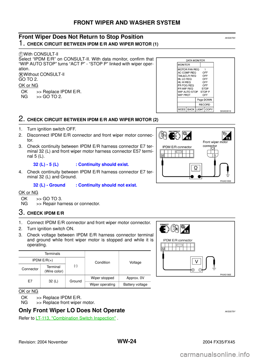
1. CHECK CIRCUIT BETWEEN IPDM E/R AND WIPER MOTOR (1)
With CONSULT-ll
Select “IPDM E/R” on CONSULT-II. With data monitor, confirm that
“WIP AUTO STOP” turns “ACT P” - “STOP P” linked with wiper oper-
ation.
Without CONSULT-ll
GO TO 2.
OK or NG
OK >> Replace IPDM E/R.
NG >> GO TO 2.
2. CHECK CIRCUIT BETWEEN IPDM E/R AND WIPER MOTOR (2)
1. Turn ignition switch OFF.
2. Disconnect IPDM E/R connector and front wiper motor connec-
tor.
3. Check continuity between IPDM E/R harness connector E7 ter-
minal 32 (L) and front wiper motor harness connector E57 termi-
nal 5 (L).
4. Check continuity between IPDM E/R harness connector E7 ter-
minal 32 (L) and Ground.
OK or NG
OK >> GO TO 3.
NG >> Repair harness or connector.
3. CHECK IPDM E/R
1. Connect IPDM E/R connector and front wiper motor connector.
2. Turn ignition switch ON.
3. Check voltage between IPDM E/R harness connector terminal
and ground while front wiper motor is stopped and while it is
operating.
OK or NG
OK >> Replace IPDM E/R.
NG >> Replace front wiper motor.
Only Front Wiper LO Does Not OperateAKS0079Y
Refer to LT- 11 3 , "Combination Switch Inspection" .
SKIA5301E
32 (L) - 5 (L) : Continuity should exist.
32 (L) - Ground : Continuity should not exist.
PKIA5195E
Terminals
Condition Voltage IPDM E/R(+)
(-)
ConnectorTe r m i n a l
(Wire color)
E7 32 (L) GroundWiper stopped Approx. 0V
Wiper operating Battery voltage
PKIA5196E
Page 4431 of 4449

WW-40
REAR WIPER AND WASHER SYSTEM
Revision: 2004 November 2004 FX35/FX45
How to Proceed With Trouble DiagnosisAKS0057L
1. Confirm the symptoms and customer complaint.
2. Understand operation description and function description. Refer to WW-35, "
System Description" .
3. Perform the Preliminary Check. Refer to WW-40, "
Preliminary Check" .
4. Check symptom and repair or replace the cause of malfunction.
5. Does the rear wiper and washer operate normally? If YES: GO TO 6. If NO: GO TO 4.
6. INSPECTION END
Preliminary CheckAKS0057M
INSPECTION POWER SUPPLY AND GROUND CIRCUIT
Inspection Procedure
1. CHECK FUSE
�Check if wiper and washer fusible link and fuse is blown.
Refer to WW-37, "Wiring Diagram — WIP/ R —" .
OK or NG
OK >> GO TO 2.
NG >> If fuse or fusible link is blown, be sure to eliminate cause of malfunction before installing new fuse
or fusible link. Refer to PG-3, "
POWER SUPPLY ROUTING CIRCUIT" .
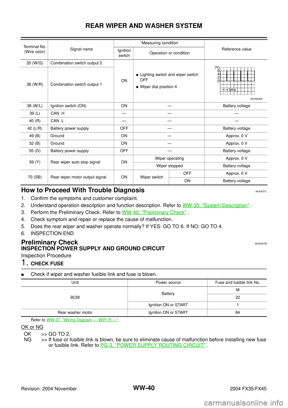
35 (W/G) Combination switch output 2
ON
�Lighting switch and wiper switch
OFF
�Wiper dial position 4 36 (W/R) Combination switch output 1
38 (W/L) Ignition switch (ON) ON — Battery voltage
39 (L) CAN H — — —
40 (R) CAN L — — —
42 (L/R) Battery power supply OFF — Battery voltage
49 (B) Ground ON — Approx. 0 V
52 (B) Ground ON — Approx. 0 V
55 (G) Battery power supply OFF — Battery voltage
59 (Y) Rear wiper auto stop signal ONWiper operating Approx. 0 V
Wiper stopped Battery voltage
70 (SB) Rear wiper motor output signal ON Wiper switchOFF Approx. 0 V
ON Battery voltage Terminal No.
(Wire color)Signal nameMeasuring condition
Reference value
Ignition
switchOperation or condition
SKIA5292E
Unit Power source Fuse and fusible link No.
BCMBatteryM
22
Ignition ON or START 1
Rear washer motor Ignition ON or START 84
Page 4435 of 4449

WW-44
REAR WIPER AND WASHER SYSTEM
Revision: 2004 November 2004 FX35/FX45
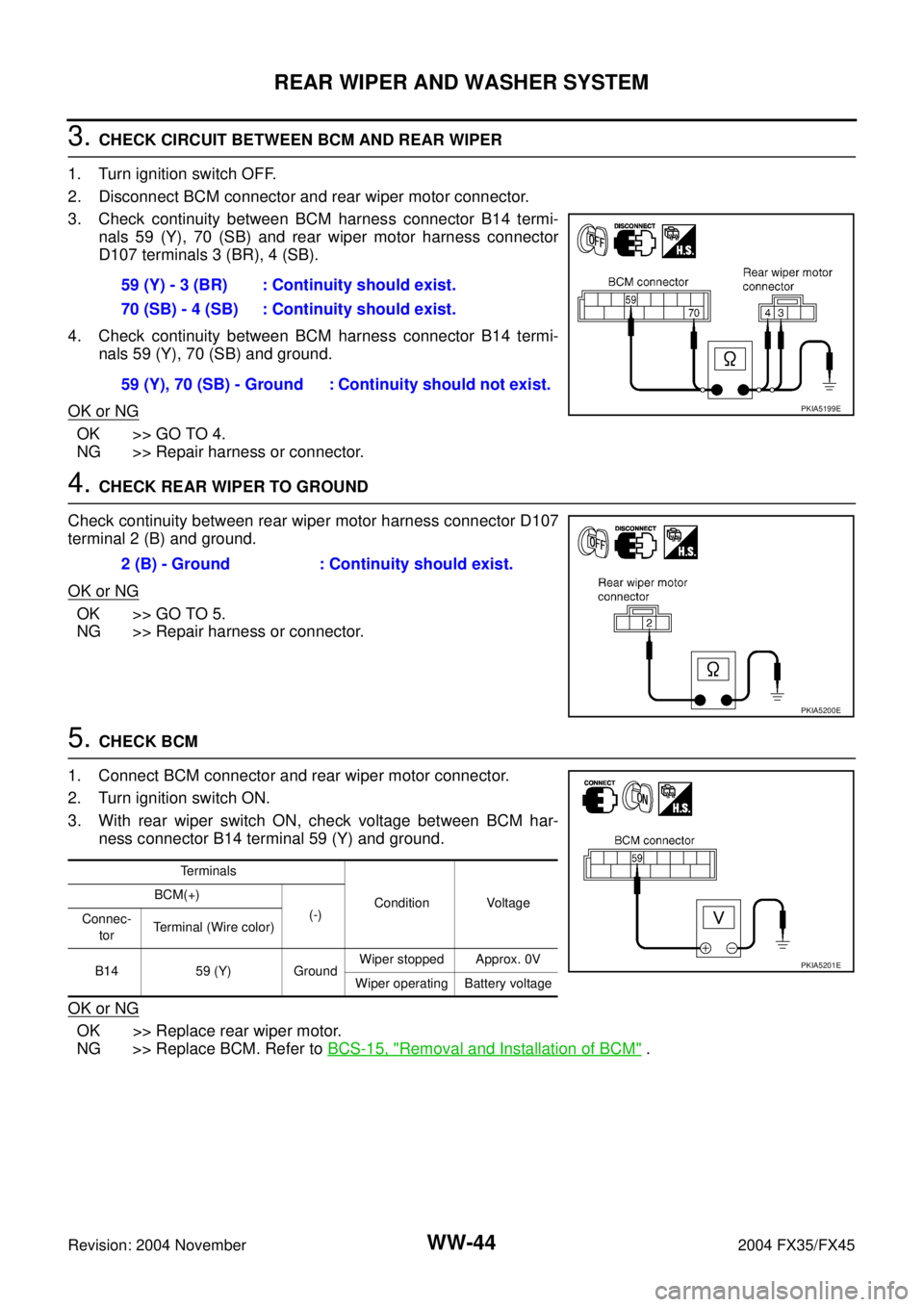
3. CHECK CIRCUIT BETWEEN BCM AND REAR WIPER
1. Turn ignition switch OFF.
2. Disconnect BCM connector and rear wiper motor connector.
3. Check continuity between BCM harness connector B14 termi-
nals 59 (Y), 70 (SB) and rear wiper motor harness connector
D107 terminals 3 (BR), 4 (SB).
4. Check continuity between BCM harness connector B14 termi-
nals 59 (Y), 70 (SB) and ground.
OK or NG
OK >> GO TO 4.
NG >> Repair harness or connector.
4. CHECK REAR WIPER TO GROUND
Check continuity between rear wiper motor harness connector D107
terminal 2 (B) and ground.
OK or NG
OK >> GO TO 5.
NG >> Repair harness or connector.
5. CHECK BCM
1. Connect BCM connector and rear wiper motor connector.
2. Turn ignition switch ON.
3. With rear wiper switch ON, check voltage between BCM har-
ness connector B14 terminal 59 (Y) and ground.
OK or NG
OK >> Replace rear wiper motor.
NG >> Replace BCM. Refer to BCS-15, "
Removal and Installation of BCM" . 59 (Y) - 3 (BR) : Continuity should exist.
70 (SB) - 4 (SB) : Continuity should exist.
59 (Y), 70 (SB) - Ground : Continuity should not exist.
PKIA5199E
2 (B) - Ground : Continuity should exist.
PKIA5200E
Terminals
Condition Voltage BCM(+)
(-)
Connec-
torTerminal (Wire color)
B14 59 (Y) GroundWiper stopped Approx. 0V
Wiper operating Battery voltage
PKIA5201E
Page 4438 of 4449

REAR WIPER AND WASHER SYSTEM
WW-47
C
D
E
F
G
H
I
J
L
MA
B
WW
Revision: 2004 November 2004 FX35/FX45
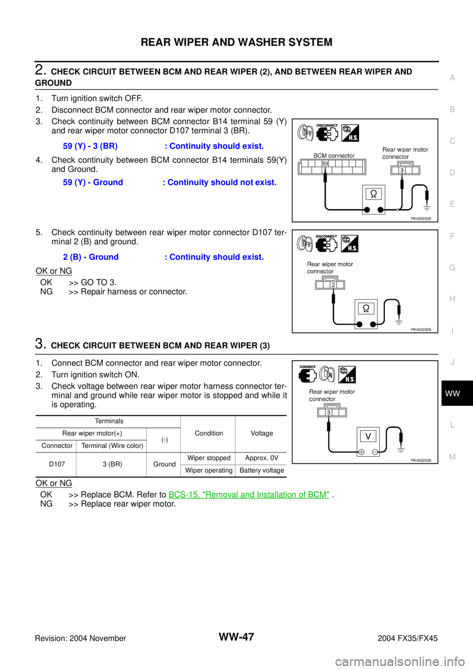
2. CHECK CIRCUIT BETWEEN BCM AND REAR WIPER (2), AND BETWEEN REAR WIPER AND
GROUND
1. Turn ignition switch OFF.
2. Disconnect BCM connector and rear wiper motor connector.
3. Check continuity between BCM connector B14 terminal 59 (Y)
and rear wiper motor connector D107 terminal 3 (BR).
4. Check continuity between BCM connector B14 terminals 59(Y)
and Ground.
5. Check continuity between rear wiper motor connector D107 ter-
minal 2 (B) and ground.
OK or NG
OK >> GO TO 3.
NG >> Repair harness or connector.
3. CHECK CIRCUIT BETWEEN BCM AND REAR WIPER (3)
1. Connect BCM connector and rear wiper motor connector.
2. Turn ignition switch ON.
3. Check voltage between rear wiper motor harness connector ter-
minal and ground while rear wiper motor is stopped and while it
is operating.
OK or NG
OK >> Replace BCM. Refer to BCS-15, "Removal and Installation of BCM" .
NG >> Replace rear wiper motor.59 (Y) - 3 (BR) : Continuity should exist.
59 (Y) - Ground : Continuity should not exist.
PKIA5202E
2 (B) - Ground : Continuity should exist.
PKIA5200E
Terminals
Condition Voltage Rear wiper motor(+)
(-)
Connector Terminal (Wire color)
D107 3 (BR) GroundWiper stopped Approx. 0V
Wiper operating Battery voltage
PKIA5203E