Page 3043 of 4449
FFD-8
FRONT OIL SEAL
Revision: 2004 November 2004 FX35/FX45
INSTALLATION
1. Apply multi-purpose grease to sealing lips of the oil seal. Drive
the oil seal into the differential case using special service tool so
that the oil seal flush with the gear carrier end.
NOTE:
�When installing the front oil seal, be careful not to get it
inclined.
�Discard the old front oil seal. Always replace it with a new
one.
2. Install the companion flange while align the matching mark of
the drive pinion with the matching mark B of the companion
flange.
3. Apply oil to the drive pinion threads and the seating surface of
drive pinion lock nut.
4. Using the drive pinion flange wrench. Install drive pinion lock nut
with tool.
CAUTION:
Do not reuse the drive pinion lock nut. Always replace it
with a new one.
5. Install the front propeller shaft. Refer to PR-5, "
INSTALLATION"
.Tool number A : ST33400001 (J26082)
B : KV38102510 ( – )
SDIA1645E
SDIA1609E
Tool number : KV40104000 ( – )
SDIA1647E
Page 3045 of 4449

FFD-10
FRONT FINAL DRIVE ASSEMBLY
Revision: 2004 November 2004 FX35/FX45
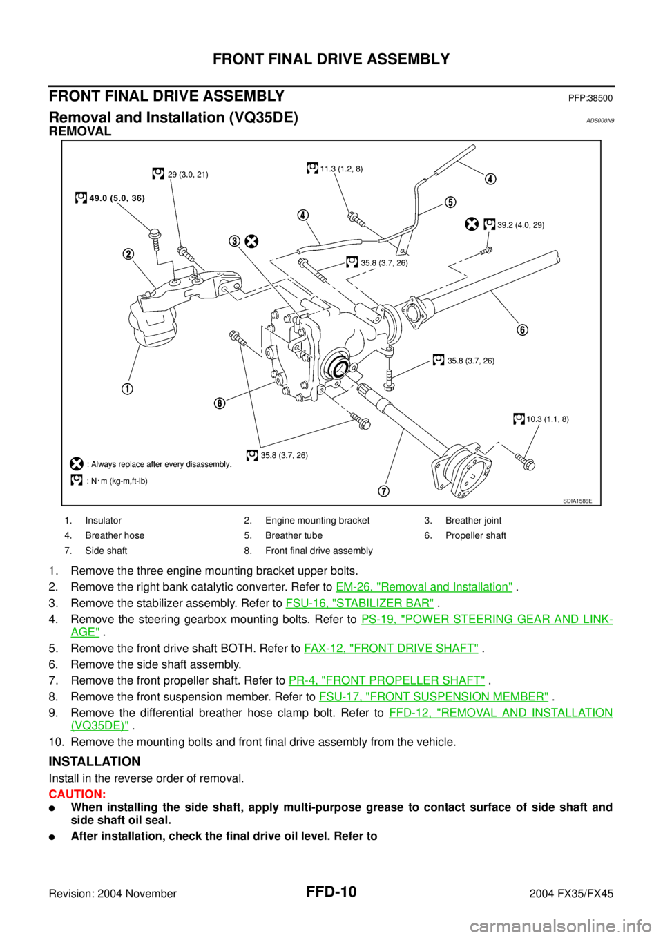
FRONT FINAL DRIVE ASSEMBLYPFP:38500
Removal and Installation (VQ35DE)ADS000N9
REMOVAL
1. Remove the three engine mounting bracket upper bolts.
2. Remove the right bank catalytic converter. Refer to EM-26, "
Removal and Installation" .
3. Remove the stabilizer assembly. Refer to FSU-16, "
STABILIZER BAR" .
4. Remove the steering gearbox mounting bolts. Refer to PS-19, "
POWER STEERING GEAR AND LINK-
AGE" .
5. Remove the front drive shaft BOTH. Refer to FAX-12, "
FRONT DRIVE SHAFT" .
6. Remove the side shaft assembly.
7. Remove the front propeller shaft. Refer to PR-4, "
FRONT PROPELLER SHAFT" .
8. Remove the front suspension member. Refer to FSU-17, "
FRONT SUSPENSION MEMBER" .
9. Remove the differential breather hose clamp bolt. Refer to FFD-12, "
REMOVAL AND INSTALLATION
(VQ35DE)" .
10. Remove the mounting bolts and front final drive assembly from the vehicle.
INSTALLATION
Install in the reverse order of removal.
CAUTION:
�When installing the side shaft, apply multi-purpose grease to contact surface of side shaft and
side shaft oil seal.
�After installation, check the final drive oil level. Refer to
SDIA1586E
1. Insulator 2. Engine mounting bracket 3. Breather joint
4. Breather hose 5. Breather tube 6. Propeller shaft
7. Side shaft 8. Front final drive assembly
Page 3046 of 4449

FRONT FINAL DRIVE ASSEMBLY
FFD-11
C
E
F
G
H
I
J
K
L
MA
B
FFD
Revision: 2004 November 2004 FX35/FX45
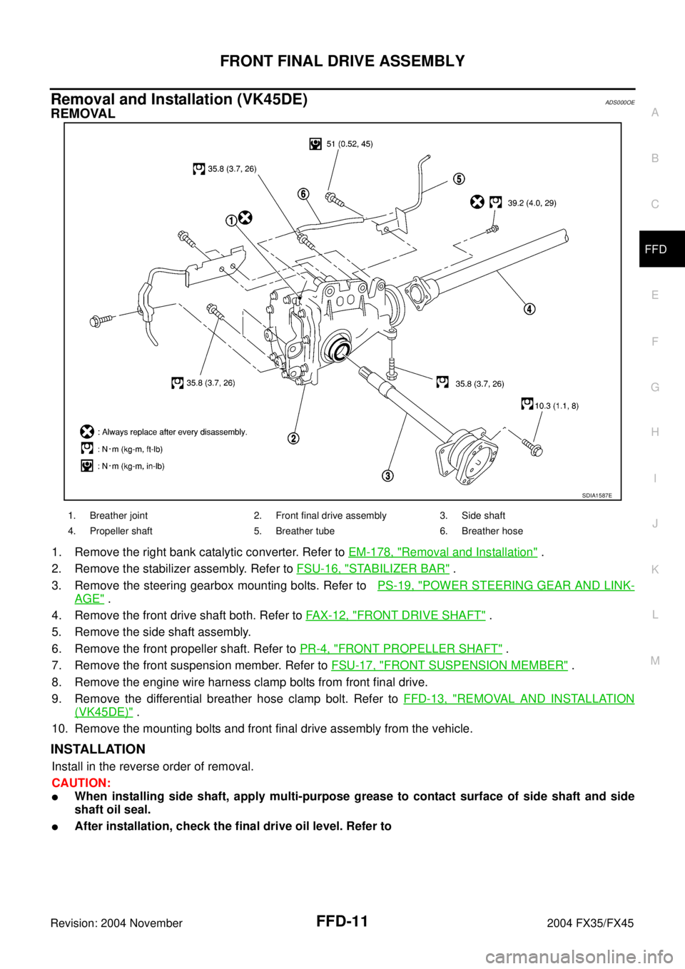
Removal and Installation (VK45DE)ADS000OE
REMOVAL
1. Remove the right bank catalytic converter. Refer to EM-178, "Removal and Installation" .
2. Remove the stabilizer assembly. Refer to FSU-16, "
STABILIZER BAR" .
3. Remove the steering gearbox mounting bolts. Refer to PS-19, "
POWER STEERING GEAR AND LINK-
AGE" .
4. Remove the front drive shaft both. Refer to FAX-12, "
FRONT DRIVE SHAFT" .
5. Remove the side shaft assembly.
6. Remove the front propeller shaft. Refer to PR-4, "
FRONT PROPELLER SHAFT" .
7. Remove the front suspension member. Refer to FSU-17, "
FRONT SUSPENSION MEMBER" .
8. Remove the engine wire harness clamp bolts from front final drive.
9. Remove the differential breather hose clamp bolt. Refer to FFD-13, "
REMOVAL AND INSTALLATION
(VK45DE)" .
10. Remove the mounting bolts and front final drive assembly from the vehicle.
INSTALLATION
Install in the reverse order of removal.
CAUTION:
�When installing side shaft, apply multi-purpose grease to contact surface of side shaft and side
shaft oil seal.
�After installation, check the final drive oil level. Refer to
SDIA1587E
1. Breather joint 2. Front final drive assembly 3. Side shaft
4. Propeller shaft 5. Breather tube 6. Breather hose
Page 3047 of 4449
FFD-12
FRONT FINAL DRIVE ASSEMBLY
Revision: 2004 November 2004 FX35/FX45
Front Final Drive Breather HoseADS000NM
REMOVAL AND INSTALLATION (VQ35DE)
NOTE:
Refer to illustration above for front final drive breather hose routing.
1. Breather hose 2. Breather tube 3. Front final drive assembly
4. Breather tube bracket end 5. Breather pipe bracket 6. Differential case boss
7. Machined face
SDIA1710E
Page 3050 of 4449
FRONT FINAL DRIVE ASSEMBLY
FFD-15
C
E
F
G
H
I
J
K
L
MA
B
FFD
Revision: 2004 November 2004 FX35/FX45
1. Washer 2. Carrier cover 3. Gear oil defence
4. Breather joint 5. Dowel pin 6. Drive pinion height adjusting washer
7. Drive pinion 8. Drive gear 9. Side bearing adjusting washer
10. Differential case 11. Side bearing 12. O-ring
13. Front oil seal 14. Side retainer 15. Side bearing adjusting shim
16. Air breather hose 17. Bushing 18. Breather tube
19. Companion flange 20. Drive pinion bearing 21. Drive pinion bearing adjusting
washer
22. Drive pinion adjusting washer 23. Extension tube retainer 24. Dust sealed
25. Side shaft 26. Extension tube 27. Carrier case
28. Side gear thrust washer 29. Lock pin 30. Pinion mate gear
31. Pinion mate thrust washer 32. Pinion mate shaft 33. Circlip
34. Side gear 35. Filler plug 36. Drain plug
37. Drive pinion lock nut 38. Side oil seal 39. Side shaft oil seal
40. Bearing
Page 3052 of 4449
FRONT FINAL DRIVE ASSEMBLY
FFD-17
C
E
F
G
H
I
J
K
L
MA
B
FFD
Revision: 2004 November 2004 FX35/FX45
7. Drive pinion 8. Drive gear 9. Side bearing adjusting washer
10. Differential case 11. Side bearing 12. O-ring
13. Front oil seal 14. Side retainer 15. Side bearing adjusting shim
16. Air breather hose 17. Bushing 18. Breather tube
19. Companion flange 20. Drive pinion bearing 21. Drive pinion bearing adjusting
washer
22. Drive pinion adjusting washer 23. Extension tube retainer 24. Dust sealed
25. Side shaft 26. Extension tube 27. Carrier case
28. Side gear thrust washer 29. Lock pin 30. Pinion mate gear
31. Pinion mete thrust washer 32. Pinion mate shaft 33. Circlip
34. Side gear 35. Filler plug 36. Drain plug
37. Drive pinion lock nut 38. Side oil seal 39. Side shaft oil seal
40. Bearing
Page 3055 of 4449

FFD-20
FRONT FINAL DRIVE ASSEMBLY
Revision: 2004 November 2004 FX35/FX45
4. Turn the companion flange in both direction 20 times or more to
seat the bearing rollers.
5. Check total preload with special service tool.
�If the preload value is out of standard, adjust pinion bearing
preload and side bearing preload.
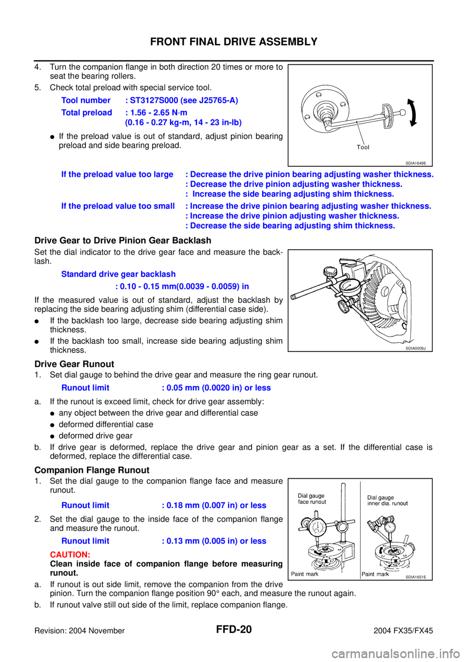
Drive Gear to Drive Pinion Gear Backlash
Set the dial indicator to the drive gear face and measure the back-
lash.
If the measured value is out of standard, adjust the backlash by
replacing the side bearing adjusting shim (differential case side).
�If the backlash too large, decrease side bearing adjusting shim
thickness.
�If the backlash too small, increase side bearing adjusting shim
thickness.
Drive Gear Runout
1. Set dial gauge to behind the drive gear and measure the ring gear runout.
a. If the runout is exceed limit, check for drive gear assembly:
�any object between the drive gear and differential case
�deformed differential case
�deformed drive gear
b. If drive gear is deformed, replace the drive gear and pinion gear as a set. If the differential case is
deformed, replace the differential case.
Companion Flange Runout
1. Set the dial gauge to the companion flange face and measure
runout.
2. Set the dial gauge to the inside face of the companion flange
and measure the runout.
CAUTION:
Clean inside face of companion flange before measuring
runout.
a. If runout is out side limit, remove the companion from the drive
pinion. Turn the companion flange position 90° each, and measure the runout again.
b. If runout valve still out side of the limit, replace companion flange.Tool number : ST3127S000 (see J25765-A)
Total preload : 1.56 - 2.65 N·m
(0.16 - 0.27 kg-m, 14 - 23 in-lb)
SDIA1649E
If the preload value too large : Decrease the drive pinion bearing adjusting washer thickness.
: Decrease the drive pinion adjusting washer thickness.
: Increase the side bearing adjusting shim thickness.
If the preload value too small : Increase the drive pinion bearing adjusting washer thickness.
: Increase the drive pinion adjusting washer thickness.
: Decrease the side bearing adjusting shim thickness.
Standard drive gear backlash
: 0.10 - 0.15 mm(0.0039 - 0.0059) in
SDIA0009J
Runout limit : 0.05 mm (0.0020 in) or less
Runout limit : 0.18 mm (0.007 in) or less
Runout limit : 0.13 mm (0.005 in) or less
SDIA1651E
Page 3056 of 4449
FRONT FINAL DRIVE ASSEMBLY
FFD-21
C
E
F
G
H
I
J
K
L
MA
B
FFD
Revision: 2004 November 2004 FX35/FX45
c. If runout valve still out side of limit after replacing companion flange, check pinion bearing and drive pinion
assembly, and pinion bearing damage.
Tooth Contact
Check tooth contact. Refer to FFD-30, "TOOTH CONTACT INSPECTION" .
DISASSEMBLY AND ASSEMBLY
REMOVAL OF DRIVE GEAR AND DIFFERENTIAL CASE ASSEMBLY
1. Remove the side retainer mounting bolt.
2. Remove the retainer by pulling it and tapping carrier case using a plastic hammer.
3. Remove the differential case assembly from the carrier case.
CAUTION:
Be careful not to damage the carrier cover mating surface.
4. Remove the side bearing outer race using puller.
5. Keep the side bearing outer races together with inner race. Do
not mix them up. Also, keep adjusting washers together with
bearings.
6. Drive out the side oil seals from the carrier case.
SDIA1656E
SDIA0181J