2004 INFINITI FX35 timing belt
[x] Cancel search: timing beltPage 3 of 4449

QUICK REFERENCE CHART FX35/FX45
QUICK REFERENCE CHART FX35/FX45PFP:00000
ENGINE TUNE-UP DATA (VQ35DE)ELS0003W
Engine modelVQ35DE
Firing order1-2-3-4-5-6
Idle speed
A/T (In “P” or “N” position)rpm
650±50
Ignition timing (BTDC at idle speed)
A/T (In “P” or “N” position)15°± 5°
CO% at idle 0.7 - 9.9 % and engine runs smoothly
Drive BeltDeflection adjustment Unit: mm (in) Tension adjustment Unit: N (kg, lb)
Used belt
New beltUsed belt
New belt
Limit After adjustment Limit After adjustment
Alternator and power
steering oil pump7 (0.28)4 - 5
(0.16 - 0.20)3.5 - 4.5
(0.138 - 0.177)294 (30, 66)730 - 818
(74.5 - 83.5,
164 - 184)838 - 926
(85.5 - 94.5,
188 - 208)
Air conditioner com-
pressor belt12 (0.47)9 - 10
(0.35 - 0.39)8 - 9
(0.31 - 0.35)196 (20, 44)348 - 436
(35.5 - 44.5,
78 - 98)470 - 559
( 4 8 - 5 7 ,
106 - 126)
Applied pushing force 98N (10kg, 22lb) —
Radiater cap relief pressure
kPa (kg/cm
2 , psi)
Standard 78 - 98 (0.8 - 1.0, 11 - 14)
Limit 59 (0.6, 9)
Cooling system leakage testing pres-
surekPa (kg/cm
2 , psi)157(1.6, 23)
Compression pressure
kPa (kg/cm
2 , psi)/rpm
Standard 1,275 (13.0, 185) /300
Minimum 981 (10.0, 142)/300
Spark plug Standard type PLFR5A - 11
Hot type PLFR4A - 11
Cold type PLFR6A - 11
2004
Page 4 of 4449

QUICK REFERENCE CHART FX35/FX45
ENGINE TUNE-UP DATA (VK45DE)
FRONT WHEEL ALIGNMENT (Unladen* )
ELS0003X
* : Fuel, engine coolant and engine oil full. Spare tire, jack, hand tools and mats in designated positions.Engine modelVK45DE
Firing order1-8-7-3-6-5-4-2
Idle speed
A/T (In “P” or “N” position) rpm650±50
Ignition timing
(BTDC at idle speed)12°±5°
CO% at idle 0.7 - 9.9 % and engine runs smoothly
Tensions of drive belts Auto adjustment by auto tensioner
Radiater cap relief pressure
kPa (kg/cm
2 , psi)
Standard 78 - 98 (0.8 - 1.0 , 11 - 14 )
Limit 59 (0.6, 9)
Cooling system leakage testing pressure
157(1.6, 23)
kPa (kg/cm
2 , psi)
Compression pressure
kPa (kg/cm
2 , psi)/rpm
Standard 1,320 (13.5, 191) /300
Minimum 1,130 (11.5, 164)/300
Spark plug Standard type PLFR5A - 11
Hot type PLFR4A - 11
Cold type PLFR6A - 11
Camber Degree minute (Decimal degree) Minimum – 1° 29′ ( – 1.48° )
Nominal – 0° 44′ ( – 0.73° )
Maximum 0° 01′ ( 0.02° )
Left and right difference 45′ ( 0.75° ) or less
Caster Degree minute (Decimal degree) Minimum 3° 02′ ( 3.03° )
Nominal 3° 47′ ( 3.78° )
Maximum 4° 32′ ( 4.53° )
Left and right difference 45′ ( 0.75° ) or less
Kingpin inclination Degree minute (Decimal degree) Minimum 12° 20′ ( 12.33° )
Nominal 13° 05′ ( 13.08° )
Maximum 13 50′ ( 13.83° )
Total toe-in Distance (A – B) Minimum 0.6 mm ( 0.024 in )
Nominal 1.6 mm ( 0.063 in )
Maximum 2.6 mm ( 0.102 in )
Angle (left plus right)
Degree minute (Degree)Minimum –
Nominal 6′ ( 0.1° )
Maximum –
Wheel turning angle (Full turn) Inside MInimum 32° 00′ ( 32.0° )
Degree minute (Decimal degree) Nominal 35° 00′ ( 35.0° )
Maximum 36° 00′ ( 36.0° )
Outside
Nominal 30° 00′ ( 30.0° )
Degree minute (Decimal degree)
2004
Page 590 of 4449

SERVICE DATA AND SPECIFICATIONS (SDS)
ATC-161
C
D
E
F
G
H
I
K
L
MA
B
AT C
Revision: 2004 November 2004 FX35/FX45
SERVICE DATA AND SPECIFICATIONS (SDS)PFP:00030
CompressorAJS00167
LubricantAJS00168
RefrigerantAJS00169
Engine Idling SpeedAJS0016A
Refer to EC-37, "Idle Speed and Ignition Timing Check" (VQ35DE) or EC-685, "Idle Speed and Ignition Tim-
ing Check" (VK45DE).
Belt TensionAJS0016B
Refer to EM-15, "DRIVE BELTS" (VQ35DE) or EM-169, "DRIVE BELTS" (VK45DE).
ModelCalsonic Kansei make CWV-618
TypeV-6 variable displacement
Displacement
cm
3 (cu in)/revMax. 184 (11.228)
Min. 14.5 (0.885)
Cylinder bore × stroke
mm (in)37 (1.46) × [2.3 - 28.6 (0.091 - 1.126)]
Direction of rotationClockwise (viewed from drive end)
Drive beltPoly V
ModelCalsonic Kansei make CWV-618
NameNissan A/C System Oil Type S (DH-PS)
Part numberKLH00-PAGS0
Capacity
m (US fl oz, lmp fl oz)Total in system 180 (6.0, 6.3)
Compressor (Service part) charg-
ing amount180 (6.0, 6.3)
Ty p eHFC-134a (R-134a)
Capacity
kg (lb)0.55 (1.21)
Page 1342 of 4449

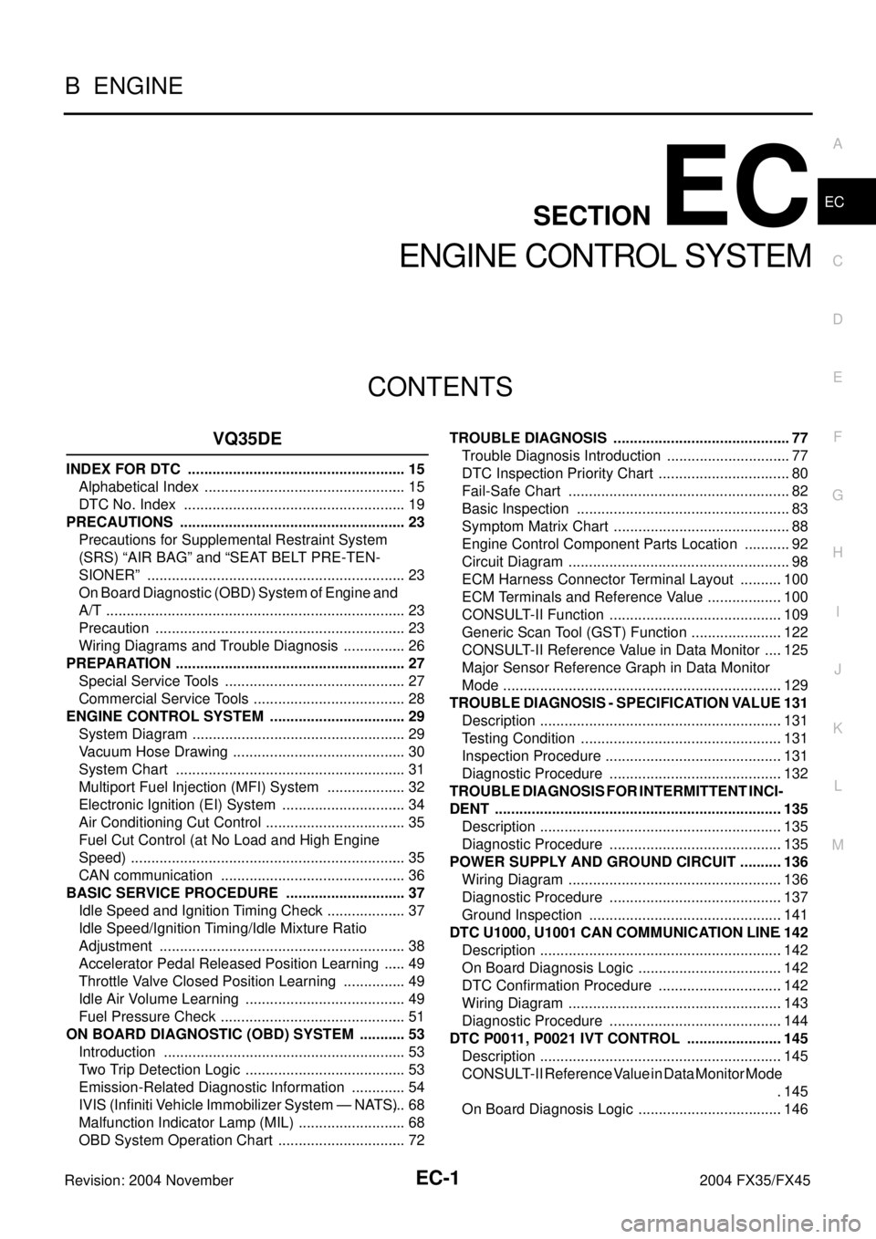
EC-1
ENGINE CONTROL SYSTEM
B ENGINE
CONTENTS
C
D
E
F
G
H
I
J
K
L
M
SECTION EC
A
EC
Revision: 2004 November 2004 FX35/FX45
ENGINE CONTROL SYSTEM
VQ35DE
INDEX FOR DTC ...................................................... 15
Alphabetical Index .................................................. 15
DTC No. Index ....................................................... 19
PRECAUTIONS ........................................................ 23
Precautions for Supplemental Restraint System
(SRS) “AIR BAG” and “SEAT BELT PRE-TEN-
SIONER” ................................................................ 23
On Board Diagnostic (OBD) System of Engine and
A/T .......................................................................... 23
Precaution .............................................................. 23
Wiring Diagrams and Trouble Diagnosis ................ 26
PREPARATION ......................................................... 27
Special Service Tools ............................................. 27
Commercial Service Tools ...................................... 28
ENGINE CONTROL SYSTEM .................................. 29
System Diagram ..................................................... 29
Vacuum Hose Drawing ........................................... 30
System Chart ......................................................... 31
Multiport Fuel Injection (MFI) System .................... 32
Electronic Ignition (EI) System ............................... 34
Air Conditioning Cut Control ................................... 35
Fuel Cut Control (at No Load and High Engine
Speed) .................................................................... 35
CAN communication .............................................. 36
BASIC SERVICE PROCEDURE .............................. 37
Idle Speed and Ignition Timing Check .................... 37
Idle Speed/Ignition Timing/Idle Mixture Ratio
Adjustment ............................................................. 38
Accelerator Pedal Released Position Learning ...... 49
Throttle Valve Closed Position Learning ................ 49
Idle Air Volume Learning ........................................ 49
Fuel Pressure Check .............................................. 51
ON BOARD DIAGNOSTIC (OBD) SYSTEM ............ 53
Introduction ............................................................ 53
Two Trip Detection Logic ........................................ 53
Emission-Related Diagnostic Information .............. 54
IVIS (Infiniti Vehicle Immobilizer System — NATS) ... 68
Malfunction Indicator Lamp (MIL) ........................... 68
OBD System Operation Chart ................................ 72TROUBLE DIAGNOSIS ............................................ 77
Trouble Diagnosis Introduction ............................... 77
DTC Inspection Priority Chart ................................. 80
Fail-Safe Chart ....................................................... 82
Basic Inspection ..................................................... 83
Symptom Matrix Chart ............................................ 88
Engine Control Component Parts Location ............ 92
Circuit Diagram ....................................................... 98
ECM Harness Connector Terminal Layout ...........100
ECM Terminals and Reference Value ...................100
CONSULT-II Function ...........................................109
Generic Scan Tool (GST) Function .......................122
CONSULT-II Reference Value in Data Monitor .....125
Major Sensor Reference Graph in Data Monitor
Mode .....................................................................129
TROUBLE DIAGNOSIS - SPECIFICATION VALUE .131
Description ............................................................131
Testing Condition ..................................................131
Inspection Procedure ............................................131
Diagnostic Procedure ...........................................132
TROUBLE DIAGNOSIS FOR INTERMITTENT INCI-
DENT .......................................................................135
Description ............................................................135
Diagnostic Procedure ...........................................135
POWER SUPPLY AND GROUND CIRCUIT ...........136
Wiring Diagram .....................................................136
Diagnostic Procedure ...........................................137
Ground Inspection ................................................141
DTC U1000, U1001 CAN COMMUNICATION LINE .142
Description ............................................................142
On Board Diagnosis Logic ....................................142
DTC Confirmation Procedure ...............................142
Wiring Diagram .....................................................143
Diagnostic Procedure ...........................................144
DTC P0011, P0021 IVT CONTROL ........................145
Description ............................................................145
CONSULT-II Reference Value in Data Monitor Mode
.145
On Board Diagnosis Logic ....................................146
Page 1348 of 4449

EC-7
C
D
E
F
G
H
I
J
K
L
M
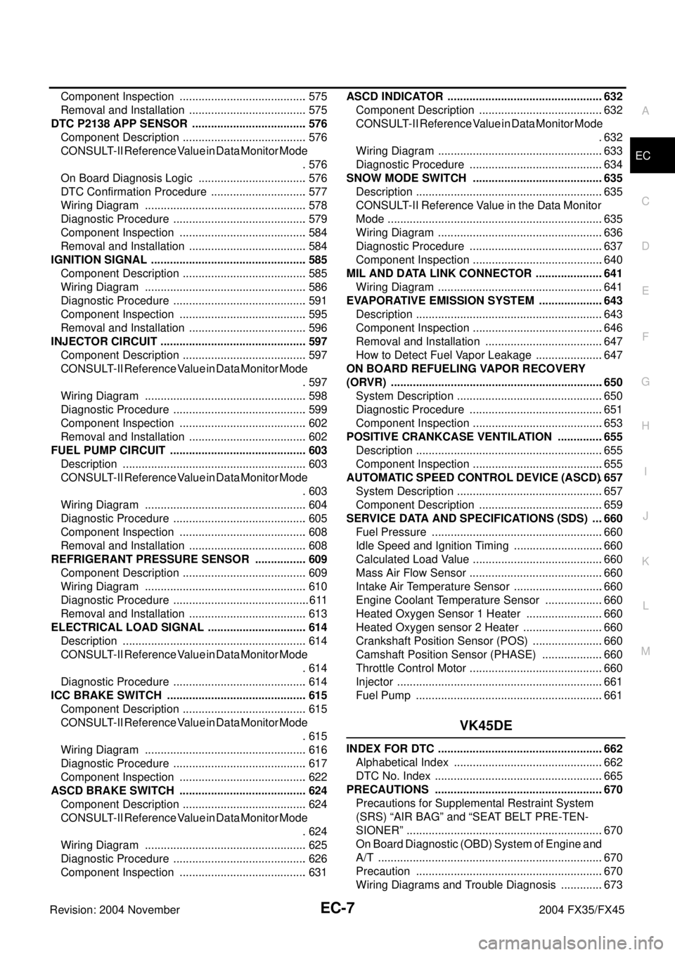
ECA
Revision: 2004 November 2004 FX35/FX45Component Inspection ......................................... 575
Removal and Installation ...................................... 575
DTC P2138 APP SENSOR ..................................... 576
Component Description ........................................ 576
CONSULT-II Reference Value in Data Monitor Mode
. 576
On Board Diagnosis Logic ................................... 576
DTC Confirmation Procedure ............................... 577
Wiring Diagram .................................................... 578
Diagnostic Procedure ........................................... 579
Component Inspection ......................................... 584
Removal and Installation ...................................... 584
IGNITION SIGNAL .................................................. 585
Component Description ........................................ 585
Wiring Diagram .................................................... 586
Diagnostic Procedure ........................................... 591
Component Inspection ......................................... 595
Removal and Installation ...................................... 596
INJECTOR CIRCUIT ............................................... 597
Component Description ........................................ 597
CONSULT-II Reference Value in Data Monitor Mode
. 597
Wiring Diagram .................................................... 598
Diagnostic Procedure ........................................... 599
Component Inspection ......................................... 602
Removal and Installation ...................................... 602
FUEL PUMP CIRCUIT ............................................ 603
Description ........................................................... 603
CONSULT-II Reference Value in Data Monitor Mode
. 603
Wiring Diagram .................................................... 604
Diagnostic Procedure ........................................... 605
Component Inspection ......................................... 608
Removal and Installation ...................................... 608
REFRIGERANT PRESSURE SENSOR ................. 609
Component Description ........................................ 609
Wiring Diagram .................................................... 610
Diagnostic Procedure ............................................ 611
Removal and Installation ...................................... 613
ELECTRICAL LOAD SIGNAL ................................ 614
Description ........................................................... 614
CONSULT-II Reference Value in Data Monitor Mode
. 614
Diagnostic Procedure ........................................... 614
ICC BRAKE SWITCH ............................................. 615
Component Description ........................................ 615
CONSULT-II Reference Value in Data Monitor Mode
. 615
Wiring Diagram .................................................... 616
Diagnostic Procedure ........................................... 617
Component Inspection ......................................... 622
ASCD BRAKE SWITCH ......................................... 624
Component Description ........................................ 624
CONSULT-II Reference Value in Data Monitor Mode
. 624
Wiring Diagram .................................................... 625
Diagnostic Procedure ........................................... 626
Component Inspection ......................................... 631ASCD INDICATOR ..................................................632
Component Description ........................................632
CONSULT-II Reference Value in Data Monitor Mode
.632
Wiring Diagram .....................................................633
Diagnostic Procedure ...........................................634
SNOW MODE SWITCH ..........................................635
Description ............................................................635
CONSULT-II Reference Value in the Data Monitor
Mode .....................................................................635
Wiring Diagram .....................................................636
Diagnostic Procedure ...........................................637
Component Inspection ..........................................640
MIL AND DATA LINK CONNECTOR ......................641
Wiring Diagram .....................................................641
EVAPORATIVE EMISSION SYSTEM .....................643
Description ............................................................643
Component Inspection ..........................................646
Removal and Installation ......................................647
How to Detect Fuel Vapor Leakage ......................647
ON BOARD REFUELING VAPOR RECOVERY
(ORVR) ....................................................................650
System Description ...............................................650
Diagnostic Procedure ...........................................651
Component Inspection ..........................................653
POSITIVE CRANKCASE VENTILATION ...............655
Description ............................................................655
Component Inspection ..........................................655
AUTOMATIC SPEED CONTROL DEVICE (ASCD) .657
System Description ...............................................657
Component Description ........................................659
SERVICE DATA AND SPECIFICATIONS (SDS) ....660
Fuel Pressure .......................................................660
Idle Speed and Ignition Timing .............................660
Calculated Load Value ..........................................660
Mass Air Flow Sensor ...........................................660
Intake Air Temperature Sensor .............................660
Engine Coolant Temperature Sensor ...................660
Heated Oxygen Sensor 1 Heater .........................660
Heated Oxygen sensor 2 Heater ..........................660
Crankshaft Position Sensor (POS) .......................660
Camshaft Position Sensor (PHASE) ....................660
Throttle Control Motor ...........................................660
Injector ..................................................................661
Fuel Pump ............................................................661
VK45DE
INDEX FOR DTC .....................................................662
Alphabetical Index ................................................662
DTC No. Index ......................................................665
PRECAUTIONS ......................................................670
Precautions for Supplemental Restraint System
(SRS) “AIR BAG” and “SEAT BELT PRE-TEN-
SIONER” ...............................................................670
On Board Diagnostic (OBD) System of Engine and
A/T ........................................................................670
Precaution ............................................................670
Wiring Diagrams and Trouble Diagnosis ..............673
Page 2727 of 4449

EM-2Revision: 2004 November 2004 FX35/FX45 FUEL INJECTOR AND FUEL TUBE ........................ 45
Removal and Installation ........................................ 45
REMOVAL ........................................................... 46
INSTALLATION .................................................... 47
INSPECTION AFTER INSTALLATION ................ 49
ROCKER COVER ..................................................... 51
Removal and Installation ........................................ 51
REMOVAL ........................................................... 51
INSTALLATION .................................................... 52
FRONT TIMING CHAIN CASE ................................. 54
Removal and Installation ........................................ 54
REMOVAL ........................................................... 54
INSTALLATION .................................................... 58
INSPECTION AFTER INSTALLATION ................ 62
TIMING CHAIN .......................................................... 63
Removal and Installation ........................................ 63
REMOVAL ........................................................... 64
INSPECTION AFTER REMOVAL ........................ 71
INSTALLATION .................................................... 71
INSPECTION AFTER INSTALLATION ................ 80
CAMSHAFT ............................................................... 82
Removal and Installation ........................................ 82
REMOVAL ........................................................... 83
INSPECTION AFTER REMOVAL ........................ 84
INSTALLATION .................................................... 87
Valve Clearance ...................................................... 89
INSPECTION ....................................................... 89
ADJUSTMENT .................................................... 92
OIL SEAL .................................................................. 94
Removal and Installation of Valve Oil Seal ............. 94
REMOVAL ........................................................... 94
INSTALLATION .................................................... 94
Removal and Installation of Front Oil Seal ............. 95
REMOVAL ........................................................... 95
INSTALLATION .................................................... 96
Removal and Installation of Rear Oil Seal .............. 96
REMOVAL ........................................................... 96
INSTALLATION .................................................... 96
CYLINDER HEAD ..................................................... 98
On-Vehicle Service ................................................. 98
CHECKING COMPRESSION PRESSURE ......... 98
Removal and Installation ........................................ 99
REMOVAL ........................................................... 99
INSPECTION AFTER REMOVAL ......................100
INSTALLATION ..................................................101
Disassembly and Assembly ..................................102
DISASSEMBLY .................................................103
ASSEMBLY .......................................................103
Inspection After Disassembly ...............................104
VALVE DIMENSIONS ........................................104
VALVE GUIDE CLEARANCE ............................105
VALVE GUIDE REPLACEMENT .......................105
VALVE SEAT CONTACT ...................................107
VALVE SEAT REPLACEMENT .........................107
VALVE SPRING SQUARENESS .......................108
VALVE SPRING DIMENSIONS AND VALVE SPRING PRESSURE LOAD ..............................109
ENGINE ASSEMBLY ...............................................110
Removal and Installation .......................................110
2WD MODEL .....................................................110
REMOVAL .......................................................... 111
INSTALLATION ..................................................113
INSPECTION AFTER INSTALLATION ..............113
AWD MODEL .....................................................115
REMOVAL ..........................................................115
INSTALLATION ..................................................118
INSPECTION AFTER INSTALLATION ..............118
CYLINDER BLOCK .................................................120
Disassembly and Assembly ..................................120
DISASSEMBLY ..................................................121
ASSEMBLY ........................................................126
How to Select Piston and Bearing ........................131
DESCRIPTION ..................................................131
HOW TO SELECT PISTON ...............................131
HOW TO SELECT CONNECTING ROD BEAR-
ING .....................................................................132
HOW TO SELECT MAIN BEARING ..................133
Inspection After Disassembly ................................136
CRANKSHAFT END PLAY ................................136
CONNECTING ROD SIDE CLEARANCE .........136
PISTON TO PISTON PIN OIL CLEARANCE .....136
PISTON RING SIDE CLEARANCE ...................137
PISTON RING END GAP ..................................137
CONNECTING ROD BEND AND TORSION .....138
CONNECTING ROD BEARING HOUSING
DIAMETER (BIG END) ......................................138
CONNECTING ROD BUSHING OIL CLEAR-
ANCE (SMALL END) .........................................138
CYLINDER BLOCK DISTORTION ....................139
MAIN BEARING HOUSING INNER DIAMETER .140
PISTON TO CYLINDER BORE CLEARANCE ..140
CRANKSHAFT MAIN JOURNAL DIAMETER ...141
CRANKSHAFT PIN JOURNAL DIAMETER ......142
CRANKSHAFT OUT-OF-ROUND AND TAPER .142
CRANKSHAFT RUNOUT ..................................142
CONNECTING ROD BEARING OIL CLEAR-
ANCE .................................................................142
MAIN BEARING OIL CLEARANCE ...................143
MAIN BEARING CRUSH HEIGHT ....................144
CONNECTING ROD BEARING CRUSH
HEIGHT .............................................................144
MAIN BEARING CAP BOLT OUTER DIAMETER .144
CONNECTING ROD BOLT OUTER DIAMETER .144
DRIVE PLATE ....................................................145
OIL JET ..............................................................145
OIL JET RELIEF VALVE ....................................145
SERVICE DATA AND SPECIFICATIONS (SDS) ....146
Standard and Limit ................................................146
GENERAL SPECIFICATIONS ...........................146
DRIVE BELT ......................................................147
INTAKE MANIFOLD COLLECTOR, INTAKE
Page 2728 of 4449

EM-3
C
D
E
F
G
H
I
J
K
L
M
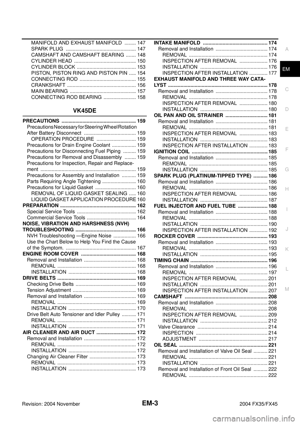
EMA
Revision: 2004 November 2004 FX35/FX45MANIFOLD AND EXHAUST MANIFOLD ......... 147
SPARK PLUG ................................................... 147
CAMSHAFT AND CAMSHAFT BEARING ........ 148
CYLINDER HEAD ............................................. 150
CYLINDER BLOCK ........................................... 153
PISTON, PISTON RING AND PISTON PIN ...... 154
CONNECTING ROD ......................................... 155
CRANKSHAFT .................................................. 156
MAIN BEARING ................................................ 157
CONNECTING ROD BEARING ........................ 158
VK45DE
PRECAUTIONS ...................................................... 159
Precautions Necessary for Steering Wheel Rotation
After Battery Disconnect ...................................... 159
OPERATION PROCEDURE ............................. 159
Precautions for Drain Engine Coolant .................. 159
Precautions for Disconnecting Fuel Piping .......... 159
Precautions for Removal and Disassembly ......... 159
Precautions for Inspection, Repair and Replace-
ment ..................................................................... 159
Precautions for Assembly and Installation ........... 159
Parts Requiring Angle Tightening ......................... 160
Precautions for Liquid Gasket .............................. 160
REMOVAL OF LIQUID GASKET SEALING ...... 160
LIQUID GASKET APPLICATION PROCEDURE . 160
PREPARATION ....................................................... 162
Special Service Tools ........................................... 162
Commercial Service Tools .................................... 164
NOISE, VIBRATION AND HARSHNESS (NVH)
TROUBLESHOOTING ............................................ 166
NVH Troubleshooting —Engine Noise ................. 166
Use the Chart Below to Help You Find the Cause
of the Symptom. ................................................... 167
ENGINE ROOM COVER ........................................ 168
Removal and Installation ...................................... 168
REMOVAL ......................................................... 168
INSTALLATION ................................................. 168
DRIVE BELTS ......................................................... 169
Checking Drive Belts ............................................ 169
Tension Adjustment .............................................. 169
Removal and Installation ...................................... 169
REMOVAL ......................................................... 169
INSTALLATION ................................................. 170
Drive Belt Auto Tensioner and Idler Pulley ........... 171
REMOVAL ......................................................... 171
INSTALLATION ................................................. 171
AIR CLEANER AND AIR DUCT ............................. 172
Removal and Installation ...................................... 172
REMOVAL ......................................................... 172
INSTALLATION ................................................. 172
Changing Air Cleaner Filter .................................. 173
REMOVAL ......................................................... 173
INSTALLATION ................................................. 173INTAKE MANIFOLD ...............................................174
Removal and Installation ......................................174
REMOVAL .........................................................174
INSPECTION AFTER REMOVAL .....................176
INSTALLATION .................................................176
INSPECTION AFTER INSTALLATION ..............177
EXHAUST MANIFOLD AND THREE WAY CATA-
LYST ........................................................................178
Removal and Installation ......................................178
REMOVAL .........................................................178
INSPECTION AFTER REMOVAL .....................180
INSTALLATION .................................................180
OIL PAN AND OIL STRAINER ...............................181
Removal and Installation ......................................181
REMOVAL .........................................................181
INSPECTION AFTER REMOVAL .....................183
INSTALLATION .................................................183
INSPECTION AFTER INSTALLATION ..............183
IGNITION COIL .......................................................185
Removal and Installation ......................................185
REMOVAL .........................................................185
INSTALLATION .................................................185
SPARK PLUG (PLATINUM-TIPPED TYPE) ...........186
Removal and Installation ......................................186
REMOVAL .........................................................186
INSPECTION AFTER REMOVAL .....................186
INSTALLATION .................................................187
FUEL INJECTOR AND FUEL TUBE ......................188
Removal and Installation ......................................188
REMOVAL .........................................................188
INSTALLATION .................................................190
INSPECTION AFTER INSTALLATION ..............192
ROCKER COVER ...................................................193
Removal and Installation ......................................193
REMOVAL .........................................................193
INSTALLATION .................................................195
TIMING CHAIN ........................................................196
Removal and Installation ......................................196
REMOVAL .........................................................197
INSPECTION AFTER REMOVAL .....................201
INSTALLATION .................................................201
INSPECTION AFTER INSTALLATION ..............207
CAMSHAFT ............................................................208
Removal and Installation ......................................208
REMOVAL .........................................................208
INSPECTION AFTER REMOVAL .....................209
INSTALLATION .................................................212
Valve Clearance ...................................................214
INSPECTION ....................................................214
ADJUSTMENT ..................................................217
OIL SEAL ................................................................221
Removal and Installation of Valve Oil Seal ...........221
REMOVAL .........................................................221
INSTALLATION .................................................221
Removal and Installation of Front Oil Seal ...........222
REMOVAL .........................................................222
Page 2739 of 4449
![INFINITI FX35 2004 Service Manual EM-14
[VQ35DE]
NOISE, VIBRATION AND HARSHNESS (NVH) TROUBLESHOOTING
Revision: 2004 November 2004 FX35/FX45
Use the Chart Below to Help You Find the Cause of the Symptom.ABS004TW
1. Locate the area whe INFINITI FX35 2004 Service Manual EM-14
[VQ35DE]
NOISE, VIBRATION AND HARSHNESS (NVH) TROUBLESHOOTING
Revision: 2004 November 2004 FX35/FX45
Use the Chart Below to Help You Find the Cause of the Symptom.ABS004TW
1. Locate the area whe](/manual-img/42/57021/w960_57021-2738.png)
EM-14
[VQ35DE]
NOISE, VIBRATION AND HARSHNESS (NVH) TROUBLESHOOTING
Revision: 2004 November 2004 FX35/FX45
Use the Chart Below to Help You Find the Cause of the Symptom.ABS004TW
1. Locate the area where noise occurs.
2. Confirm the type of noise.
3. Specify the operating condition of engine.
4. Check specified noise source.
If necessary, repair or replace these parts.
A: Closely related B: Related C: Sometimes related —: Not relatedLocation
of noiseType of
noiseOperating condition of engine
Source of
noiseCheck itemRefer-
ence page Before
warm-
upAfter
warm-
upWhen
start-
ingWhen
idlingWhen
racingWhile
driving
Top of
engine
Rocker
cover
Cylinder
headTicking or
clickingCA—AB—Tappet
noiseValve clearanceEM-89
Rattle C A — A B CCamshaft
bearing
noiseCamshaft runout
Camshaft journal oil
clearanceEM-84EM-84
Crank-
shaft pul-
ley
Cylinder
block
(Side of
engine)
Oil panSlap or
knock—A—B B—Piston pin
noisePiston to piston pin oil
clearance
Connecting rod bush-
ing oil clearance (Small
end)EM-136
EM-138
Slap or
rapA——B B APiston
slap noisePiston to cylinder bore
clearance
Piston ring side clear-
ance
Piston ring end gap
Connecting rod bend
and torsionEM-140EM-137
EM-137
EM-138
Knock A B C B B BConnect-
ing rod
bearing
noiseConnecting rod bush-
ing oil clearance (Small
end)
Connecting rod bear-
ing housing diameter
(Big end)EM-138EM-138
Knock A B — A B CMain
bearing
noiseMain bearing oil clear-
ance
Crankshaft runoutEM-143EM-142
Front of
engine
Timing
chain
caseTapping or
tickingAA—BBBTiming
chain and
chain ten-
sioner
noiseTiming chain cracks
and wear
Timing chain tensioner
operationEM-71
Front of
engineSqueak-
ing or fizz-
ingAB—B—CDrive belts
(Sticking
or slip-
ping)Drive belts deflection
EM-15
CreakingABABABDrive belts
(Slipping)Idler pulley bearing
operation
Squall
CreakAB—BABWater
pump
noiseWater pump operationCO-22,
"WATER
PUMP"