2004 DAEWOO NUBIRA battery
[x] Cancel search: batteryPage 1138 of 2643

ANTILOCK BRAKE SYSTEM 4F – 57
DAEWOO V–121 BL4
DTC C0800 – Low Voltage Fault
StepActionValue(s)YesNo
1Check the voltage at the battery.
Is the voltage within the specified value?11–14 vGo to Step 3Go to Step 2
2Charge or replace the battery as required.
Is the repair complete?–System OK–
3Check fuse EF2 in the engine fuse block.
Is the fuse blown?–Go to Step 4Go to Step 7
41. Replace fuse EF2.
2. Turn the ignition to ON.
Does the fuse blow again?–Go to Step 5Go to Step 6
51. Turn the ignition to OFF.
2. Trace the RED wires in the ABS wiring harness
from terminal 1 of C107 at the engine fuse
block to terminals 17 and 18 of the EBCM con-
nector.
3. Repair any short circuit found along this path.
Is the repair complete?–System OK–
61. Turn the ignition switch to OFF.
2. Install the scan tool.
3. Clear all DTCs.
4. Road test the vehicle.
Does DTC C0800 reset?–System OK–
7Check fuse F11 in the I/P fuse block.
Is the fuse blown?–Go to Step 8Go to Step 11
81. Replace fuse F11.
2. Turn the ignition to ON.
Does the fuse blow again?–Go to Step 9Go to Step 10
91. Turn the ignition to OFF.
2. Trace the BRN wire from fuse F11 to terminal
43 of connector C201, from terminal 62 of con-
nector C202 to terminal 6 of connector C110,
and from there to terminal 15 of the EBCM
connector.
3. Repair any short circuit found along this path.
Is the repair complete?–System OK–
101. Turn the ignition switch to OFF.
2. Install the scan tool.
3. Clear all DTCs.
4. Road test the vehicle.
Does DTC C0800 reset?–System OK–
111. Disconnect the EBCM connector from the
EBCM.
2. Turn the ignition to ON.
3. Check for the presence of battery voltage be-
tween ground and terminal 17, and between
ground and terminal 18.
Is the voltage within the specified value?11–14 vGo to Step 13Go to Step 12
Page 1141 of 2643

4F – 60IANTILOCK BRAKE SYSTEM
DAEWOO V–121 BL4
MAINTENANCE AND REPAIR
ON–VEHICLE SERVICE
SERVICE PRECAUTIONS
CAUTION : Brake fluid may irritate eyes and skin. In
case of contact, take the following actions:
S Eye contact – rinse thoroughly with water.
S Skin contact – wash with soap and water.
S Ingestion – consult a physician immediately.
CAUTION : To help avoid personal injury due to poor
braking, DO NOT tap into the vehicle’s brake system
to operate a trailer brake system.
Notice : When fasteners are removed, always reinstall
them at the same location from which they were removed.
If a fastener needs to be replaced, use the correct part
number fastener for that application. If the correct part
number fastener is not available, a fastener of equal size
and strength (or stronger) may be used. Fasteners that
are not reused, and those requiring thread–locking com-
pound will be called out. The correct torque values must
be used when installing fasteners that require them. If the
above procedures are not followed, parts or system dam-
age could result.
Notice : Use only DOT 3 equivalent hydraulic brake fluid.
The use of DOT 5 (silicone) brake fluid is not recom-
mended. Reduced brake performance or durability may
result.
Notice : Avoid spilling brake fluid on any of the vehicle’s
painted surfaces, wiring, cables, or electrical connectors.
Brake fluid will damage paint and electrical connections.
If any fluid is spilled on the vehicle, flush the area with wa-
ter to lessen the damage.
Computer System Service Precautions
Take care to avoid electronic brake control module
(EBCM) circuit overloading. In testing for opens or shorts,
do not ground or apply voltage to any circuit unless
instructed to do so by the diagnostic procedure. Test cir-
cuits only with a high–impedance multimeter. Never re-
move or apply power to any control module with the igni-
tion switch in the ON position. Always turn the ignition to
the OFF position before removing or connecting battery
cables, fuses, or connectors.
General Service Precautions
S Disconnect the EBCM connector before performing
any vehicle welding work using an electric arc weld-
er.
S Do not attempt to disassemble any component des-
ignated as nonserviceable. The hydraulic modulator
and the EBCM can be separated from each other
and replaced separately but cannot be serviced.
They have no replaceable parts, and there is no
access to the components they contain.
Page 1142 of 2643

ANTILOCK BRAKE SYSTEM 4F – 61
DAEWOO V–121 BL4
BLEEDING SYSTEM
Replacement modulators are shipped already filled and
bled. In normal procedures requiring removal of the modu-
lator, such as to replace the EBCM, air will not enter the
modulator, and normal bleeding will be all that is needed.
For this procedure, refer to Section 4A, Hydraulic Brakes.
If air enters the hydraulic modulator, or if an unfilled modu-
lator is installed, use the brake bleeding program in the
scan tool to bleed the modulator. Manual bleeding of the
hydraulic modulator is not possible.
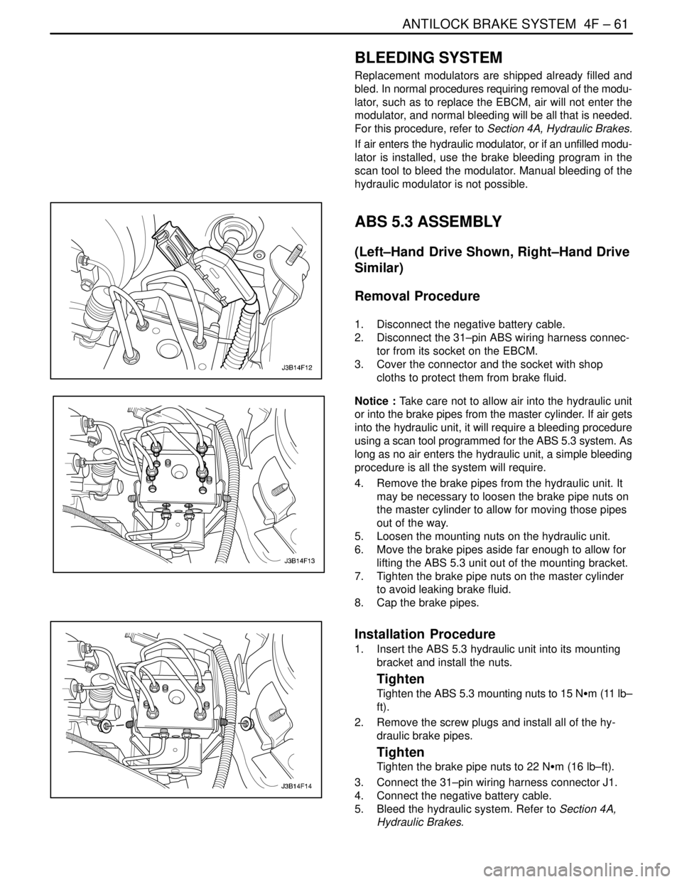
ABS 5.3 ASSEMBLY
(Left–Hand Drive Shown, Right–Hand Drive
Similar)
Removal Procedure
1. Disconnect the negative battery cable.
2. Disconnect the 31–pin ABS wiring harness connec-
tor from its socket on the EBCM.
3. Cover the connector and the socket with shop
cloths to protect them from brake fluid.
Notice : Take care not to allow air into the hydraulic unit
or into the brake pipes from the master cylinder. If air gets
into the hydraulic unit, it will require a bleeding procedure
using a scan tool programmed for the ABS 5.3 system. As
long as no air enters the hydraulic unit, a simple bleeding
procedure is all the system will require.
4. Remove the brake pipes from the hydraulic unit. It
may be necessary to loosen the brake pipe nuts on
the master cylinder to allow for moving those pipes
out of the way.
5. Loosen the mounting nuts on the hydraulic unit.
6. Move the brake pipes aside far enough to allow for
lifting the ABS 5.3 unit out of the mounting bracket.
7. Tighten the brake pipe nuts on the master cylinder
to avoid leaking brake fluid.
8. Cap the brake pipes.
Installation Procedure
1. Insert the ABS 5.3 hydraulic unit into its mounting
bracket and install the nuts.
Tighten
Tighten the ABS 5.3 mounting nuts to 15 NSm (11 lb–
ft).
2. Remove the screw plugs and install all of the hy-
draulic brake pipes.
Tighten
Tighten the brake pipe nuts to 22 NSm (16 lb–ft).
3. Connect the 31–pin wiring harness connector J1.
4. Connect the negative battery cable.
5. Bleed the hydraulic system. Refer to Section 4A,
Hydraulic Brakes.
Page 1143 of 2643

4F – 62IANTILOCK BRAKE SYSTEM
DAEWOO V–121 BL4
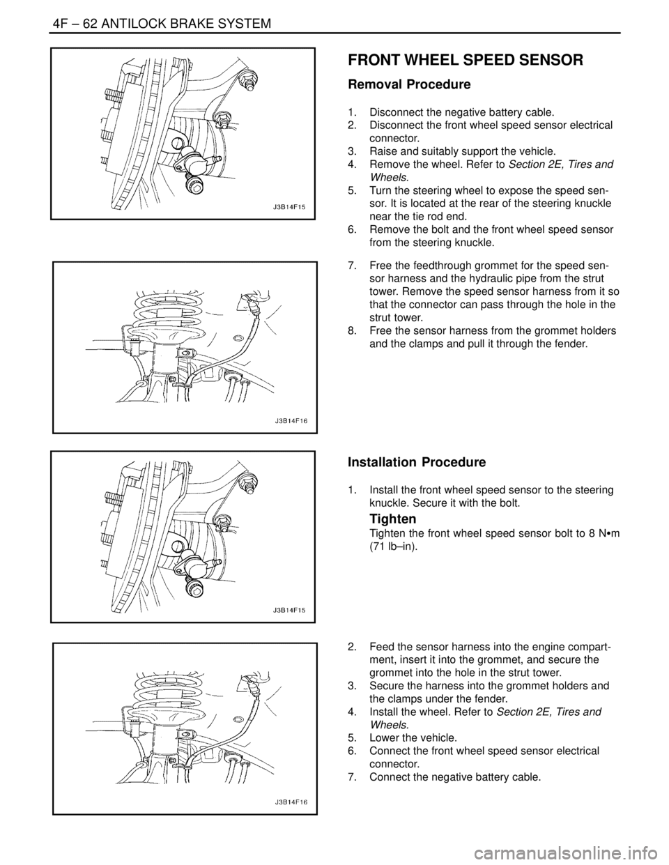
FRONT WHEEL SPEED SENSOR
Removal Procedure
1. Disconnect the negative battery cable.
2. Disconnect the front wheel speed sensor electrical
connector.
3. Raise and suitably support the vehicle.
4. Remove the wheel. Refer to Section 2E, Tires and
Wheels.
5. Turn the steering wheel to expose the speed sen-
sor. It is located at the rear of the steering knuckle
near the tie rod end.
6. Remove the bolt and the front wheel speed sensor
from the steering knuckle.
7. Free the feedthrough grommet for the speed sen-
sor harness and the hydraulic pipe from the strut
tower. Remove the speed sensor harness from it so
that the connector can pass through the hole in the
strut tower.
8. Free the sensor harness from the grommet holders
and the clamps and pull it through the fender.
Installation Procedure
1. Install the front wheel speed sensor to the steering
knuckle. Secure it with the bolt.
Tighten
Tighten the front wheel speed sensor bolt to 8 NSm
(71 lb–in).
2. Feed the sensor harness into the engine compart-
ment, insert it into the grommet, and secure the
grommet into the hole in the strut tower.
3. Secure the harness into the grommet holders and
the clamps under the fender.
4. Install the wheel. Refer to Section 2E, Tires and
Wheels.
5. Lower the vehicle.
6. Connect the front wheel speed sensor electrical
connector.
7. Connect the negative battery cable.
Page 1144 of 2643

ANTILOCK BRAKE SYSTEM 4F – 63
DAEWOO V–121 BL4
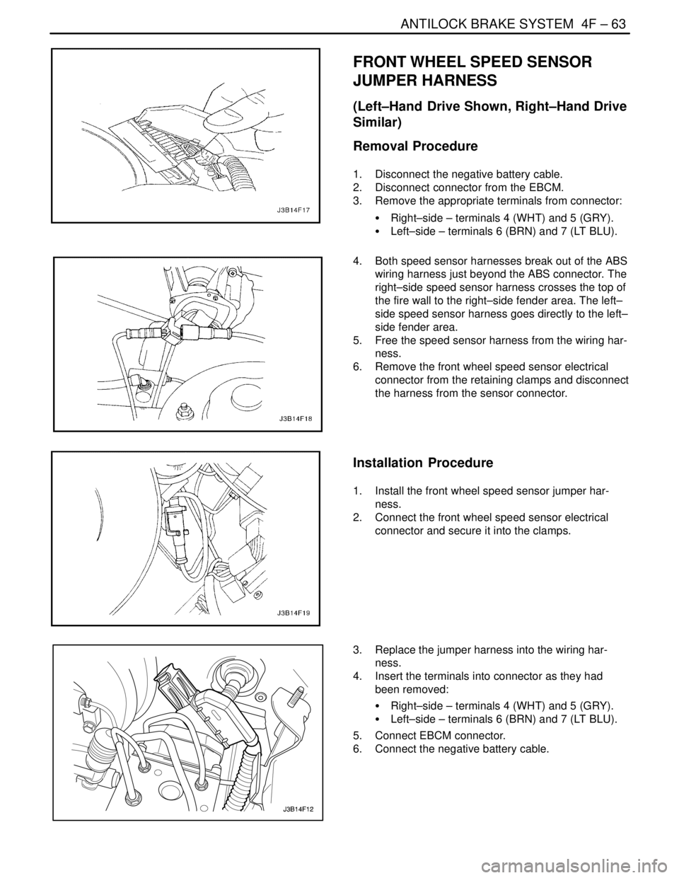
FRONT WHEEL SPEED SENSOR
JUMPER HARNESS
(Left–Hand Drive Shown, Right–Hand Drive
Similar)
Removal Procedure
1. Disconnect the negative battery cable.
2. Disconnect connector from the EBCM.
3. Remove the appropriate terminals from connector:
S Right–side – terminals 4 (WHT) and 5 (GRY).
S Left–side – terminals 6 (BRN) and 7 (LT BLU).
4. Both speed sensor harnesses break out of the ABS
wiring harness just beyond the ABS connector. The
right–side speed sensor harness crosses the top of
the fire wall to the right–side fender area. The left–
side speed sensor harness goes directly to the left–
side fender area.
5. Free the speed sensor harness from the wiring har-
ness.
6. Remove the front wheel speed sensor electrical
connector from the retaining clamps and disconnect
the harness from the sensor connector.
Installation Procedure
1. Install the front wheel speed sensor jumper har-
ness.
2. Connect the front wheel speed sensor electrical
connector and secure it into the clamps.
3. Replace the jumper harness into the wiring har-
ness.
4. Insert the terminals into connector as they had
been removed:
S Right–side – terminals 4 (WHT) and 5 (GRY).
S Left–side – terminals 6 (BRN) and 7 (LT BLU).
5. Connect EBCM connector.
6. Connect the negative battery cable.
Page 1145 of 2643

4F – 64IANTILOCK BRAKE SYSTEM
DAEWOO V–121 BL4
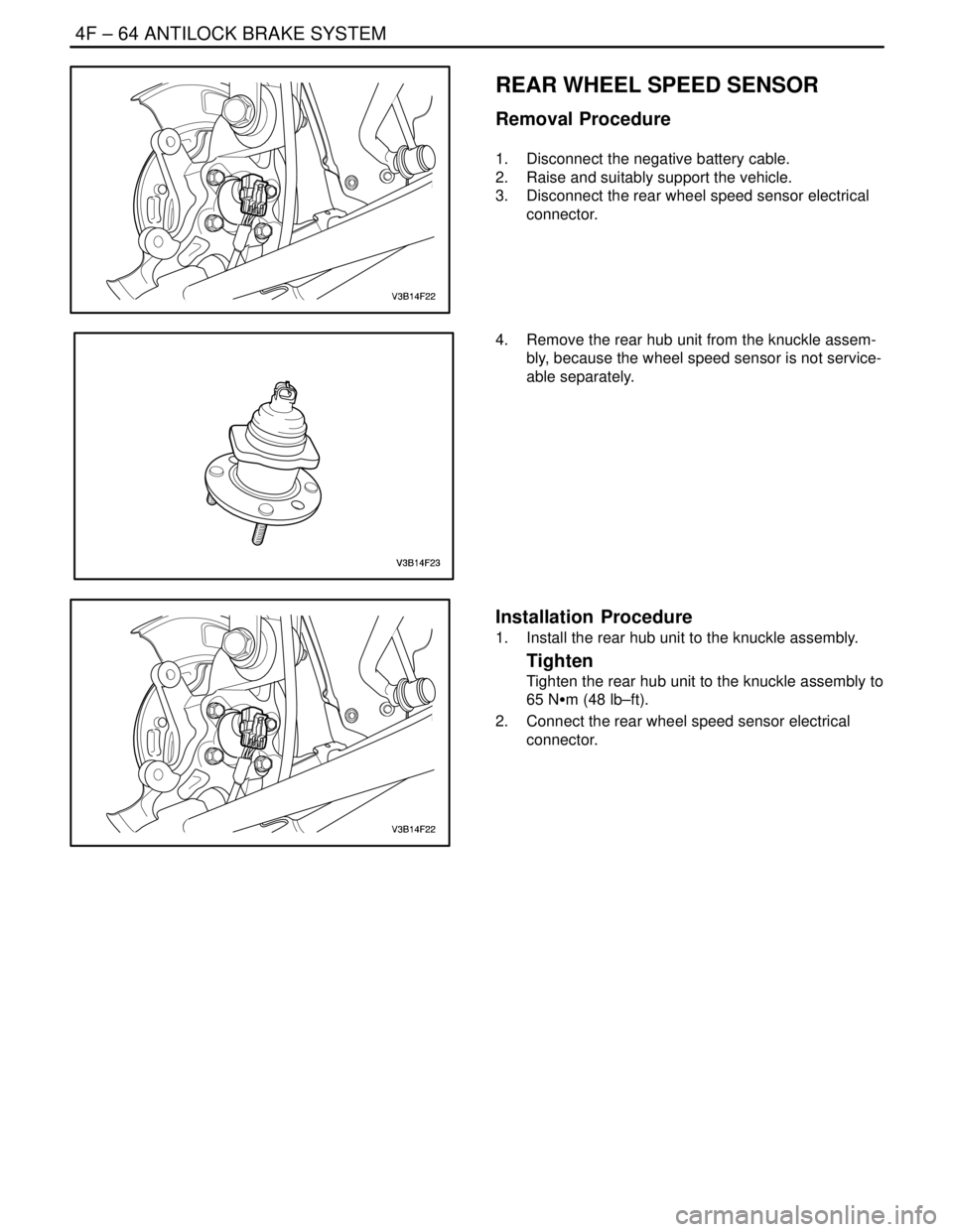
REAR WHEEL SPEED SENSOR
Removal Procedure
1. Disconnect the negative battery cable.
2. Raise and suitably support the vehicle.
3. Disconnect the rear wheel speed sensor electrical
connector.
4. Remove the rear hub unit from the knuckle assem-
bly, because the wheel speed sensor is not service-
able separately.
Installation Procedure
1. Install the rear hub unit to the knuckle assembly.
Tighten
Tighten the rear hub unit to the knuckle assembly to
65 NSm (48 lb–ft).
2. Connect the rear wheel speed sensor electrical
connector.
Page 1152 of 2643

ANTILOCK BRAKE SYSTEM 4F – 71
DAEWOO V–121 BL4
TIRES AND ABS/EBD
Replacement Tires
Tire size is important for proper performance of the ABS
system. Replacement tires should be the same size, load
range, and construction as the original tires. Replace tires
in axle sets and only with tires of the same tire perfor-
mance criteria (TPC) specification number. Use of any
other size or type may seriously affect the ABS operation.
TIRES AND ABS/EBD
Notice : There is no serviceable or removable EEPROM.
The EBCM must be replaced as an assembly.
The EBCM is attached to the hydraulic unit in the engine
compartment. The controlling element of ABS 5.3 is a mi-
croprocessor–based EBCM. Inputs to the system include
the four wheel speed sensors, the stoplamp switch, the
ignition switch, and the unswitched battery voltage. There
is an output to a bi–directional serial data link, located in
pin K of Data Link Connector (DLC) for service diagnostic
tools and assembly plant testing.
The EBCM monitors the speed of each wheel. If any wheel
begins to approach lockup and the brake switch is closed
(brake pedal depressed), the EBCM controls the sole-
noids to reduce brake pressure to the wheel approaching
lockup. Once the wheel regains traction, brake pressure
is increased until the wheel again begins to approach lock-
up. This cycle repeats until either the vehicle comes to a
stop, the brake pedal is released, or no wheels approach
lockup.
Additionally, the EBCM monitors itself, each input (except
the serial data link), and each output for proper operation.
If it detects any system malfunction, the EBCM will store
a DTC in nonvolatile memory (EEPROM) (DTCs will not
disappear if the battery is disconnected). Refer to ”Self
Diagnostics” in this section for more detailed information.
FRONT WHEEL SPEED SENSOR
The front wheel speed sensors are of a variable reluctance
type. Each sensor is attached to the steering knuckle,
close to a toothed ring. The result, as teeth pass by the
sensor, is an AC voltage with a frequency proportional to
the speed of the wheel. The magnitude of the voltage and
frequency increase with increasing speed. The sensor is
not repairable, nor is the air gap adjustable.
FRONT WHEEL SPEED SENSOR
RINGS
The toothed ring mentioned above is pressed onto the
wheel–side (outer) constant velocity joint. Each ring con-
tains 47 equally spaced teeth. Exercise care during ser-
vice procedures to avoid prying or contacting this ring. Ex-cessive contact may cause damage to one or more teeth.
If the ring is damaged, the wheel–side constant velocity
joint must be replaced.
REAR WHEEL SPEED SENSOR AND
RINGS
The rear wheel speed sensors operate in the same man-
ner as the front wheel speed sensors. They incorporate a
length of flexible harness with the connector attached to
the end of the harness. The rear wheel speed rings are in-
corporated into the hub assemblies and cannot be re-
placed separately, but require replacement of the rear
hub/bearing assembly.
VALUE RELAY AND PUMP MOTOR
RELAY
The valve relay and the motor pump relay are located in-
side the electronic brake control module (EBCM) and are
not replaceable. If one should fail, replace the EBCM.
WIRING HARNESS
The wiring harness is the mechanism by which the elec-
tronic brake control module (EBCM) is electrically con-
nected to power and to ground, to the wheel speed sen-
sors, the fuses, the switches, the indicators, and the serial
communications port. The components, considered part
of the wiring harness, are the wires that provide electrical
interconnection, and connectors (terminals, pins, con-
tacts, or lugs) that provide an electrical/mechanical inter-
face from the wire to a system component.
INDICATORS
The electronic brake control module (EBCM) continuously
monitors itself and the other ABS components. If the
EBCM detects a problem with the system, the amber ABS
indicator will light continuously to alert the driver to the
problem. An illuminated ABS indicator indicates that the
ABS system has detected a problem that affects the op-
eration of ABS. No antilock braking will be available. Nor-
mal, non–antilock brake performance will remain. In order
to regain ABS braking ability, the ABS must be serviced.
The red BRAKE indicator will be illuminated when the sys-
tem detects a low brake fluid level in the master cylinder
or when the parking brake switch is closed (the parking
brake is engaged) or EBD system is diabled.
WARNING : EBD INDICATOR LAMP WIRING IS CON-
NECTED TO THE PARKING BRAKE LAMP. IF THE
PARKING BRAKE LAMP IS TURNED ON WHEN YOU
DRIVING, CHECKING ON WHETHER THE PARKING
BRAKE LEVER IS ENAGED OR THE BRAKE FLUID
LEVEL IS LOW. IF THE SYSTEM HAS NO PROBLEM,
THE EBD SYSTEM IS WORKING IMPROPERLY. THE
EBD SYSTEM MUST BE SERVICED.
Page 1162 of 2643

SECTION 5
ELECTRICAL WIRING DIAGRAMS
CONTENTS
1. STARTING & CHARGING SYSTEM5–8 . . . . . . . . . . . . . . . . . . . . . . . . . . . . . . . . . . . . . . . . . . . . . . . . . . . . . . . . . . . . . . . .
1) BATTERY, IGNITION SWITCH, STARTER MOTOR, GENERATOR & PNP SWITCH CIRCUIT 5–8. . . . . . . . . .
2. ECM (ENGINE CONTROL MODULE) : MR–140 5–10. . . . . . . . . . . . . . . . . . . . . . . . . . . . . . . . . . . . . . . . . . . . . . . . . . . .
1) BATTERY POWER SUPPLY, GROUND, EI SYSTEM & CKP SENSOR CIRCUIT 5–10. . . . . . . . . . . . . . . . . . . . .
2) FUEL PUMP, INJECTOR & HEATED O2 SENSOR CIRCUIT 5–12. . . . . . . . . . . . . . . . . . . . . . . . . . . . . . . . . . . . . .
3) IAC, SENSOR(MAP, ECT, TP, KNOCK, ACP & ROUGH ROAD) & LEGR CIRCUIT 5–14. . . . . . . . . . . . . . . . . . .
4) EVAP CANISTER PURGE SOLENOID, CMP SENSOR, CLUSTER & VSS CIRCUIT 5–16. . . . . . . . . . . . . . . . .
5) CLUSTER, FUEL PUMP & TCM CIRCUIT 5–18. . . . . . . . . . . . . . . . . . . . . . . . . . . . . . . . . . . . . . . . . . . . . . . . . . . . . .
6) DLC, MIL LAMP & IMMOBILIZER CONTROL CIRCUIT 5–20. . . . . . . . . . . . . . . . . . . . . . . . . . . . . . . . . . . . . . . . . . .
3. ECM (ENGINE CONTROL MODULE) : HV–240 5–22. . . . . . . . . . . . . . . . . . . . . . . . . . . . . . . . . . . . . . . . . . . . . . . . . . . .
1) BATTERY POWER SUPPLY, GROUND, EI SYSTEM & CKP SENSOR CIRCUIT 5–22. . . . . . . . . . . . . . . . . . . . .
2) FUEL PUMP, INJECTOR & O2 SENSOR CIRCUIT 5–24. . . . . . . . . . . . . . . . . . . . . . . . . . . . . . . . . . . . . . . . . . . . . . .
3) IAC, SENSOR(MAP, ECT, TP, IAT, KNOCK & ACP) & EGR VALVE CIRCUIT 5–26. . . . . . . . . . . . . . . . . . . . . . . .
4) EVAP CANISTER PURGE SOLENOID, CMP SENSOR, CLUSTER & VSS CIRCUIT 5–28. . . . . . . . . . . . . . . . .
5) CLUSTER, FUEL PUMP & TCM CIRCUIT 5–30. . . . . . . . . . . . . . . . . . . . . . . . . . . . . . . . . . . . . . . . . . . . . . . . . . . . . .
6) DLC, MIL LAMP, IMMOBILIZER CONTROL & RON SWITCH CIRCUIT 5–32. . . . . . . . . . . . . . . . . . . . . . . . . . . . .