2004 DAEWOO NUBIRA battery
[x] Cancel search: batteryPage 865 of 2643

ENGINE CONTROLS 1F – 619
DAEWOO V–121 BL4
CAMSHAFT POSITION SENSOR
(1.8L DOHC)
Removal Procedure
1. Disconnect the negative battery cable.
2. Remove the engine cover.
3. Disconnect the sensor electrical connector.
4. Remove the timing belt front cover. Refer to Sec-
tion 1C, DOHC Engine Mechanical.
5. Remove the camshaft position sensor bolts.
6. Remove the camshaft position sensor from the top.
Installation Procedure
1. Install the camshaft position sensor and bolts.
Tighten
Tighten the camshaft position bolts to 8 NSm (71 lb–
in).
2. Install the timing belt front cover, the crankshaft
pulley, the accessory drive belt, and the air filter.
Refer to Section 1C, DOHC Engine Mechanical.
3. Connect the sensor electrical connector.
4. Install the engine cover.
5. Connect the negative battery cable.
Page 866 of 2643

1F – 620IENGINE CONTROLS
DAEWOO V–121 BL4
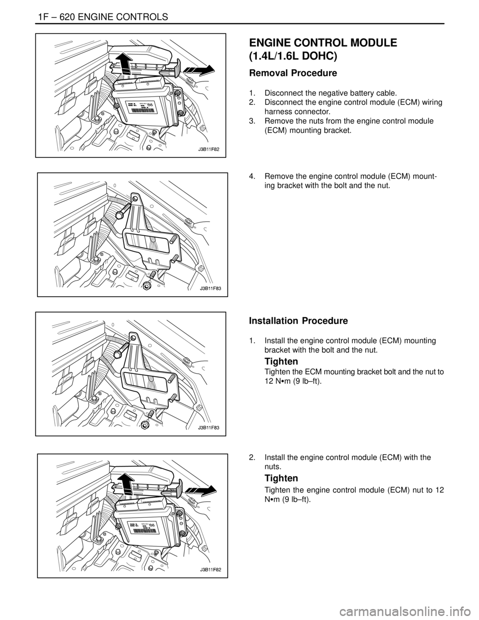
ENGINE CONTROL MODULE
(1.4L/1.6L DOHC)
Removal Procedure
1. Disconnect the negative battery cable.
2. Disconnect the engine control module (ECM) wiring
harness connector.
3. Remove the nuts from the engine control module
(ECM) mounting bracket.
4. Remove the engine control module (ECM) mount-
ing bracket with the bolt and the nut.
Installation Procedure
1. Install the engine control module (ECM) mounting
bracket with the bolt and the nut.
Tighten
Tighten the ECM mounting bracket bolt and the nut to
12 NSm (9 lb–ft).
2. Install the engine control module (ECM) with the
nuts.
Tighten
Tighten the engine control module (ECM) nut to 12
NSm (9 lb–ft).
Page 867 of 2643

ENGINE CONTROLS 1F – 621
DAEWOO V–121 BL4
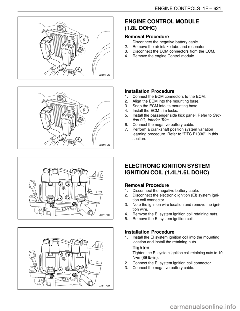
ENGINE CONTROL MODULE
(1.8L DOHC)
Removal Procedure
1. Disconnect the negative battery cable.
2. Remove the air intake tube and resonator.
3. Disconnect the ECM connectors from the ECM.
4. Remove the engine Control module.
Installation Procedure
1. Connect the ECM connectors to the ECM.
2. Align the ECM into the mounting base.
3. Snap the ECM into its mounting base.
4. Install the ECM trim locks.
5. Install the passenger side kick panel. Refer to Sec-
tion 9G, Interior Trim.
6. Connect the negative battery cable.
7. Perform a crankshaft position system variation
learning procedure. Refer to ”DTC P1336” in this
section.
ELECTRONIC IGNITION SYSTEM
IGNITION COIL (1.4L/1.6L DOHC)
Removal Procedure
1. Disconnect the negative battery cable.
2. Disconnect the electronic ignition (EI) system igni-
tion coil connector.
3. Note the ignition wire location and remove the igni-
tion wire.
4. Remvoe the EI system ignition coil retaining nuts.
5. Remove the EI system ignition coil.
Installation Procedure
1. Install the EI system ignition coil into the mounting
location and install the retaining nuts.
Tighten
Tighten the EI system ignition coil retaining nuts to 10
NSm (89 lb–in).
2. Connect the EI system ignition coil connector.
3. Connect the negative battery cable.
Page 868 of 2643

1F – 622IENGINE CONTROLS
DAEWOO V–121 BL4
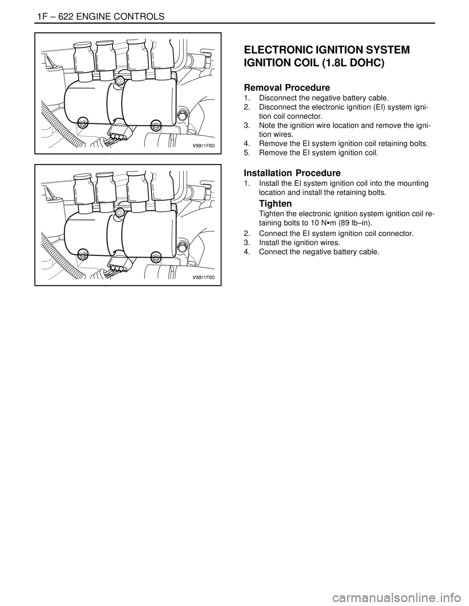
ELECTRONIC IGNITION SYSTEM
IGNITION COIL (1.8L DOHC)
Removal Procedure
1. Disconnect the negative battery cable.
2. Disconnect the electronic ignition (EI) system igni-
tion coil connector.
3. Note the ignition wire location and remove the igni-
tion wires.
4. Remove the EI system ignition coil retaining bolts.
5. Remove the EI system ignition coil.
Installation Procedure
1. Install the EI system ignition coil into the mounting
location and install the retaining bolts.
Tighten
Tighten the electronic ignition system ignition coil re-
taining bolts to 10 NSm (89 lb–in).
2. Connect the EI system ignition coil connector.
3. Install the ignition wires.
4. Connect the negative battery cable.
Page 870 of 2643

1F – 624IENGINE CONTROLS
DAEWOO V–121 BL4
Because of the constant measuring and adjusting of the
air/fuel ratio, the fuel injection system is called a ”closed
loop” system.
The ECM uses voltage inputs from several sensors to de-
termine how much fuel to provide to the engine. The fuel
is delivered under one of several conditions, called
”modes.”
Starting Mode
When the ignition is turned ON, the ECM turns the fuel
pump relay on for two seconds. The fuel pump then builds
fuel pressure. The ECM also checks the Engine Coolant
Temperature (ECT) sensor and the Throttle Position (TP)
sensor and determines the proper air/fuel ratio for starting
the engine. This ranges from 1.5 to 1 at –97 °F (–36 °C)
coolant temperature to 14.7 to 1 at 201 °F (94 °C) coolant
temperature. The ECM controls the amount of fuel deliv-
ered in the starting mode by changing how long the fuel in-
jector is turned on and off. This is done by ”pulsing” the fuel
injectors for very short times.
Clear Flood Mode
If the engine floods with excessive fuel, it may be cleared
by pushing the accelerator pedal down all the way. The
ECM will then completely turn off the fuel by eliminating
any fuel injector signal. The ECM holds this injector rate
as long as the throttle stays wide open and the engine is
below approximately 400. If the throttle position becomes
less than approximately 80 percent, the ECM returns to
the starting mode.
Run Mode
The run mode has two conditions called ”open loop” and
”closed loop.”
Open Loop
When the engine is first started and it is above 400 rpm,
the system goes into ”open loop” operation. In ”open loop,”
the ECM ignores the signal from the HO2S and calculates
the air/fuel ratio based on inputs from the ECT sensor and
the MAP sensor. The sensor stays in ”open loop” until the
following conditions are met:
S The HO2S sensor has a varying voltage output,
showing that it is hot enough to operate properly.
S The ECT sensor is above a specified temperature.
S A specific amount of time has elapsed after starting
the engine.
Closed Loop
The specific values for the above conditions vary with dif-
ferent engines and are stored in the Electronically Eras-
able Programmable Read–Only Memory (EEPROM).
When these conditions are met, the system goes into
”closed loop” operation. In ”closed loop,” the ECM calcu-
lates the air/fuel ratio (fuel injector on–time) based on the
signal from the oxygen sensor. This allows the air/fuel ratio
to stay very close to 14.7 to 1.Acceleration Mode
The ECM responds to rapid changes in throttle position
and airflow and provides extra fuel.
Deceleration Mode
The ECM responds to changes in throttle position and air-
flow and reduces the amount of fuel. When deceleration
is very fast, the ECM can cut off fuel completely for short
periods of time.
Battery Voltage Correction Mode
When battery voltage is low, the ECM can compensate for
a weak spark delivered by the ignition module by using the
following methods:
S Increasing the fuel injector pulse width.
S Increasing the idle speed rpm.
S Increasing the ignition dwell time.
Fuel Cut–Off Mode
No fuel is delivered by the fuel injectors when the ignition
is OFF. This prevents dieseling or engine run–on. Also, the
fuel is not delivered if there are no reference pulses re-
ceived from the central power supply. This prevents flood-
ing.
EVAPORATIVE EMISSION CONTROL
SYSTEM OPERATION
The basic Evaporative (EVAP) Emission control system
used is the charcoal canister storage method. This meth-
od transfers fuel vapor from the fuel tank to an activated
carbon (charcoal) storage device (canister) to hold the va-
pors when the vehicle is not operating. When the engine
is running, the fuel vapor is purged from the carbon ele-
ment by intake airflow and consumed in the normal com-
bustion process.
Gasoline vapors from the fuel tank flow into the tube la-
beled TANK. These vapors are absorbed into the carbon.
The canister is purged by the engine control module
(ECM) when the engine has been running for a specified
amount of time. Air is drawn into the canister and mixed
with the vapor. This mixture is then drawn into the intake
manifold.
The ECM supplies a ground to energize the EVAP emis-
sion canister purge solenoid valve. This valve is Pulse
Width Modulated (PWM) or turned on and off several
times a second. The EVAP emission canister purge PWM
duty cycle varies according to operating conditions deter-
mined by mass airflow, fuel trim, and intake air tempera-
ture.
Poor idle, stalling, and poor driveability can be caused by
the following conditions:
S An inoperative EVAP emission canister purge sole-
noid valve.
S A damaged canister.
S Hoses that are split, cracked, or not connected to
the proper tubes.
Page 872 of 2643

1F – 626IENGINE CONTROLS
DAEWOO V–121 BL4
EXHAUST GAS RECIRCULATION
VA LV E
The Exhaust Gas Recirculation (EGR) system is used on
engines equipped with an automatic transaxle to lower
NOx (oxides of nitrogen) emission levels caused by high
combustion temperature. The EGR valve is controlled by
the engine control module (ECM). The EGR valve feeds
small amounts of exhaust gas into the intake manifold to
decrease combustion temperature. The amount of ex-
haust gas recirculated is controlled by variations in vacu-
um and exhaust back pressure. If too much exhaust gas
enters, combustion will not take place. For this reason,
very little exhaust gas is allowed to pass through the valve,
especially at idle.
The EGR valve is usually open under the following condi-
tions:
S Warm engine operation.
S Above idle speed.
Results of Incorrect Operation
Too much EGR flow tends to weaken combustion, causing
the engine to run roughly or to stop. With too much EGR
flow at idle, cruise, or cold operation, any of the following
conditions may occur:
S The engine stops after a cold start.
S The engine stops at idle after deceleration.
S The vehicle surges during cruise.
S Rough idle.
If the EGR valve stays open all the time, the engine may
not idle. Too little or no EGR flow allows combustion tem-
peratures to get too high during acceleration and load con-
ditions. This could cause the following conditions:
S Spark knock (detonation)
S Engine overheating
S Emission test failure
INTAKE AIR TEMPERATURE
SENSOR
The Intake Air Temperature (IAT) sensor is a thermistor,
a resistor which changes value based on the temperature
of the air entering the engine. Low temperature produces
a high resistance (4,500 ohms at –40°F [–40°C]), while
high temperature causes a low resistance (70 ohms at
266°F [130°C]).
The engine control module (ECM) provides 5 volts to the
IAT sensor through a resistor in the ECM and measures
the change in voltage to determine the IAT. The voltage will
be high when the manifold air is cold and low when the air
is hot. The ECM knows the intake IAT by measuring the
voltage.
The IAT sensor is also used to control spark timing when
the manifold air is cold.
A failure in the IAT sensor circuit sets a diagnostic trouble
code P0112 or P0113.
IDLE AIR CONTROL VALVE
Notice : Do not attempt to remove the protective cap to
readjust the stop screw. Misadjustment may result in dam-
age to the Idle Air Control (IAC) valve or to the throttle
body.
The IAC valve is mounted on the throttle body where it
controls the engine idle speed under the command of the
engine control module (ECM). The ECM sends voltage
pulses to the IAC valve motor windings, causing the IAC
valve pintle to move in or out a given distance (a step or
count) for each pulse. The pintle movement controls the
airflow around the throttle valves which, in turn, control the
engine idle speed.
The desired idle speeds for all engine operating conditions
are programmed into the calibration of the ECM. These
programmed engine speeds are based on the coolant
temperature, the park/neutral position switch status, the
vehicle speed, the battery voltage, and the A/C system
pressure (if equipped).
The ECM ”learns” the proper IAC valve positions to
achieve warm, stabilized idle speeds (rpm) desired for the
various conditions (park/neutral or drive, A/C on or off, if
equipped). This information is stored in ECM ”keep alive”
memories. Information is retained after the ignition is
turned OFF. All other IAC valve positioning is calculated
based on these memory values. As a result, engine varia-
tions due to wear and variations in the minimum throttle
valve position (within limits) do not affect engine idle
speeds. This system provides correct idle control under all
conditions. This also means that disconnecting power to
the ECM can result in incorrect idle control or the necessity
to partially press the accelerator when starting until the
ECM relearns idle control.
Engine idle speed is a function of total airflow into the en-
gine based on the IAC valve pintle position, the throttle
valve opening, and the calibrated vacuum loss through ac-
cessories. The minimum throttle valve position is set at the
factory with a stop screw. This setting allows enough air-
flow by the throttle valve to cause the IAC valve pintle to
be positioned a calibrated number of steps (counts) from
the seat during ”controlled” idle operation. The minimum
throttle valve position setting on this engine should not be
considered the ”minimum idle speed,” as on other fuel in-
jected engines. The throttle stop screw is covered with a
plug at the factory following adjustment.
If the IAC valve is suspected as the cause of improper idle
speed, refer to ”Idle Air Control System Check” in this sec-
tion.
MANIFOLD ABSOLUTE PRESSURE
SENSOR
The Manifold Absolute Pressure (MAP) sensor measures
the changes in the intake manifold pressure which result
from engine load and speed changes. It converts these to
a voltage output.
Page 883 of 2643

ENGINE EXHAUST 1G – 3
DAEWOO V–121 BL4
MAINTENANCE AND REPAIR
ON–VEHICLE SERVICE
CATALYTIC CONVERTER
Removal Procedure
1. Disconnect the negative battery cable.
2. Disconnect the oxygen sensor electrical connector.
3. Remove the exhaust manifold cover with the bolts.
4. Remove the catalytic converter upper flange nuts.
Important : The nuts and the stud may unscrew as a unit
because of the high temperature associated with the ex-
hast manifold, but they can be re–used as such
5. Remove the exhaust front pipe mounting bracket
bolt.
6. Remove the nuts from the exhaust front pipe–to–
catalytic converter flange.
7. Remove the catalytic converter and the gasket.
8. Clean the sealing surfaces on the exhaust front
pipe flange and the exhaust manifold.
9. Check the exhaust front pipe and the exhaust man-
ifold for holes, damage, open seams or other dete-
rioration which could permit exhaust fumes to seep
into the passenger compartment.
Page 884 of 2643

1G – 4IENGINE EXHAUST
DAEWOO V–121 BL4
Installation Procedure
1. Install the catalytic converter and the gasket to the
exhaust front pipe flange.
Tighten
Tighten the exhaust front pipe–to–catalytic converter
nuts to 40 NSm (30 lb–ft).
Tighten the exhaust front pipe–to–cylinder block bolt
to 50 NSm (37 lb–ft).
2. Install the catalytic converter to exhaust manifold
nuts and the gasket.
Tighten
Tighten the catalytic converter to exhaust manifold
nuts to 40 NSm (30 lb–ft).
3. Install the exhaust manifold conver bolts.
Tighten
Tighten the exhaust manifold cover bolts to 15 NSm
(11 lb–ft).
4. Connect the oxygen sensor electrical connector.
5. Connect the negative battery cable.
EXHAUST FRONT PIPE
Removal Procedure
1. Remove the crossmember lower bracket with the
bolts.