2004 DAEWOO LACETTI wiper
[x] Cancel search: wiperPage 2463 of 2643
9R – 2IBODY FRONT END
DAEWOO V–121 BL4
MAINTENANCE AND REPAIR
ON–VEHICLE SERVICE
LUBRICATION
The hood hinges and the locking mechanisms require pe-
riodic lubrication for proper operation. Refer to Section 0B,
General Information for the specific types and intervals of
lubrication.
FASTENERS
Notice : Dissimilar metals in direct contact with each other
may corrode rapidly. Make sure to use the correct fasten-
ers to prevent premature corrosion.
Many aluminum components are used on current models.
Aluminum in contact with steel may corrode rapidly if it is
not protected by special finishes or isolators.
The fasteners used have a special finish which provides
adequate protection from corrosion. These special fasten-
ers differ in color in order to easily identify them from the
standard metric fasteners, which are medium blue.
When replacing fasteners, avoid substituting otherwise
similar fasteners in the same location.
ANTICORROSION MATERIALS
In order to provide rust resistance, anticorrosion materials
have been applied to the interior surfaces of most of the
metal panels. When you service these panels, properly re-
coat them with a service–type anticorrosion material if any
of the original material has been disturbed.
FRONT END SEALING
All locations where waterleaks may occur are sealed dur-
ing production with high quality, durable sealers. If it be-
comes necessary to reseal specific areas, use a high–
quality sealer of medium–bodied consistency which will
retain its flexible characteristics after curing and can be
painted, if necessary.
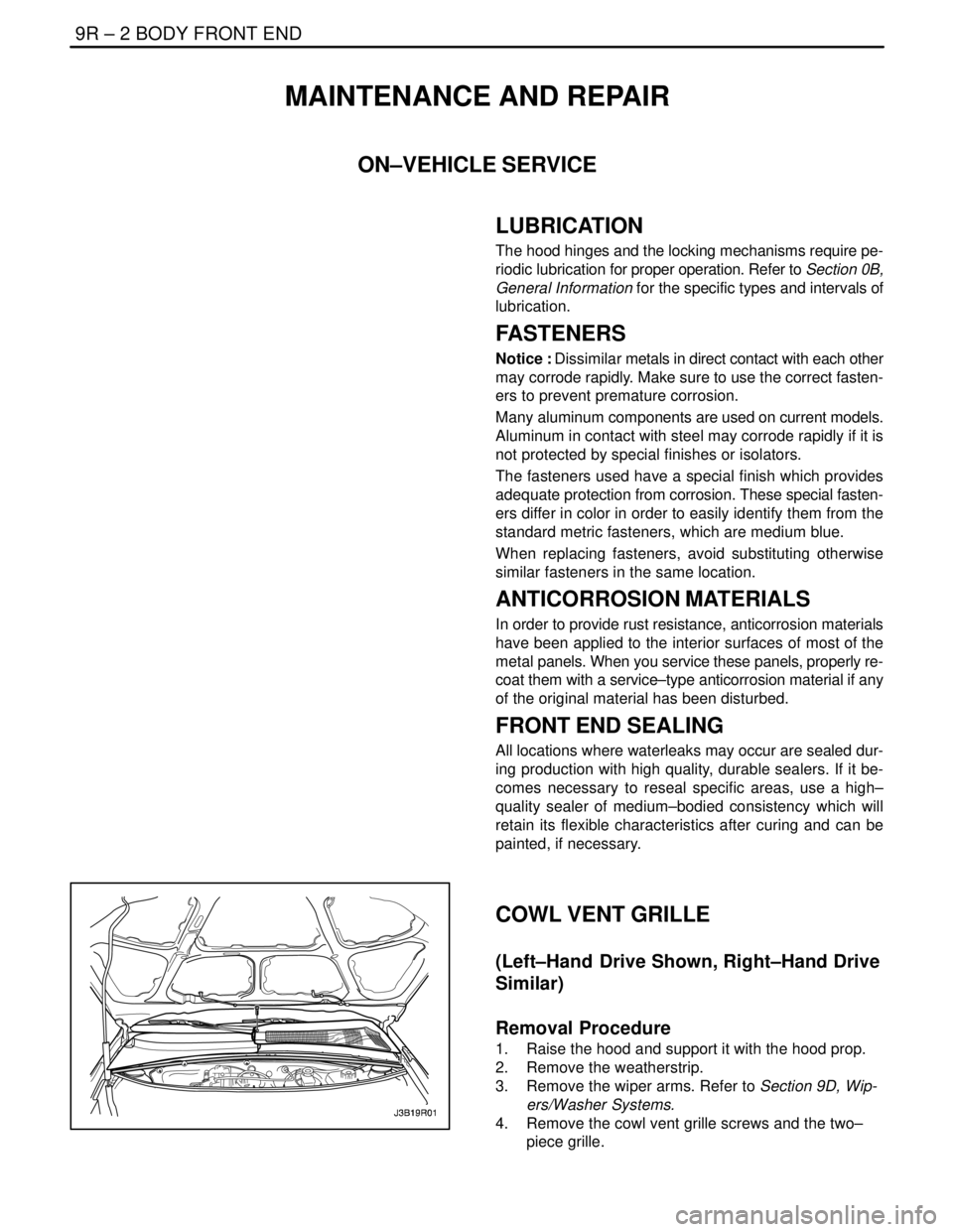
COWL VENT GRILLE
(Left–Hand Drive Shown, Right–Hand Drive
Similar)
Removal Procedure
1. Raise the hood and support it with the hood prop.
2. Remove the weatherstrip.
3. Remove the wiper arms. Refer to Section 9D, Wip-
ers/Washer Systems.
4. Remove the cowl vent grille screws and the two–
piece grille.
Page 2464 of 2643
BODY FRONT END 9R – 3
DAEWOO V–121 BL4
Installation Procedure
Notice : Dissimilar metals in direct contact with each other
may corrode rapidly. Make sure to use the correct fasten-
ers to prevent premature corrosion.
1. Install the two–piece grille and the cowl vent grille
screws.
Tighten
Tighten the cowl vent grille screws to 4SNSm (35 lb–
in).
2. Remove the wiper arms. Refer to Section 9D, Wip-
ers/Washer Systems.
3. Install the weatherstrip.
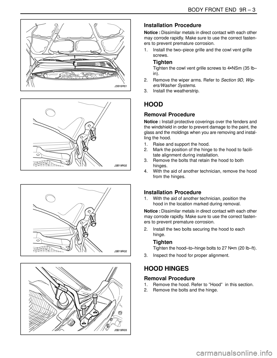
HOOD
Removal Procedure
Notice : Install protective coverings over the fenders and
the windshield in order to prevent damage to the paint, the
glass and the moldings when you are removing and instal-
ling the hood.
1. Raise and support the hood.
2. Mark the position of the hinge to the hood to facili-
tate alignment during installation.
3. Remove the bolts that retain the hood to both
hinges.
4. With the aid of another technician, remove the hood
from the hinges.
Installation Procedure
1. With the aid of another technician, position the
hood in the location marked during removal.
Notice : Dissimilar metals in direct contact with each other
may corrode rapidly. Make sure to use the correct fasten-
ers to prevent premature corrosion.
2. Install the two bolts securing the hood to each
hinge.
Tighten
Tighten the hood–to–hinge bolts to 27 NSm (20 lb–ft).
3. Inspect the hood for proper alignment.
HOOD HINGES
Removal Procedure
1. Remove the hood. Refer to ”Hood” in this section.
2. Remove the bolts and the hinge.
Page 2549 of 2643
NUBIRA/LACETTIFRONT 4–15
4–2. REPAIR PROCEDURE
1. Remove the related parts.
S Hood, radiator grill and front bumper.
S Door and fender.
S Wiper, cowl and windshield.
S Weatherstrip and pillar trims.
S Instrument panel and wiring harness.
S Carpet and others.
2. Roughly pull out and straighten the damaged area.
S Check the damage to the wheelhouse and roof before
removing the brace wheelhouse and front pillar and de-
termine the extent of the damage.
S Use the frame straightener to roughly pull out and repair
the damaged front pillar before removing the brace
wheelhouse and front panel.
Note : Pull out until the pillar is lined up with the surface
of the windshield and do not pull out more than neces-
sary.
Fig. 23
3. Remove the brace wheelhouse.
S Center punch around the spot weld imprints.
S Use the special spot cutter to drill holes at the spot weld
nuggets on the brace wheelhouse.
S Remove the MIG weld areas with a disc sander.
CAUTION : To prevent eye injury, wear goggles or
safety glasses whenever sanding, cutting, or grind–
ing.
S Using a chisel, pry off the welded flange from the front
body pillar and wheelhouse.
Fig. 24
4. Peel off the undercoat and sealer.
S Heat the undercoat and sealer at the welding areas of
the wheelhouse and longitudinal with a gas torch and
peel off the undercoat and sealer with a steel spatula.
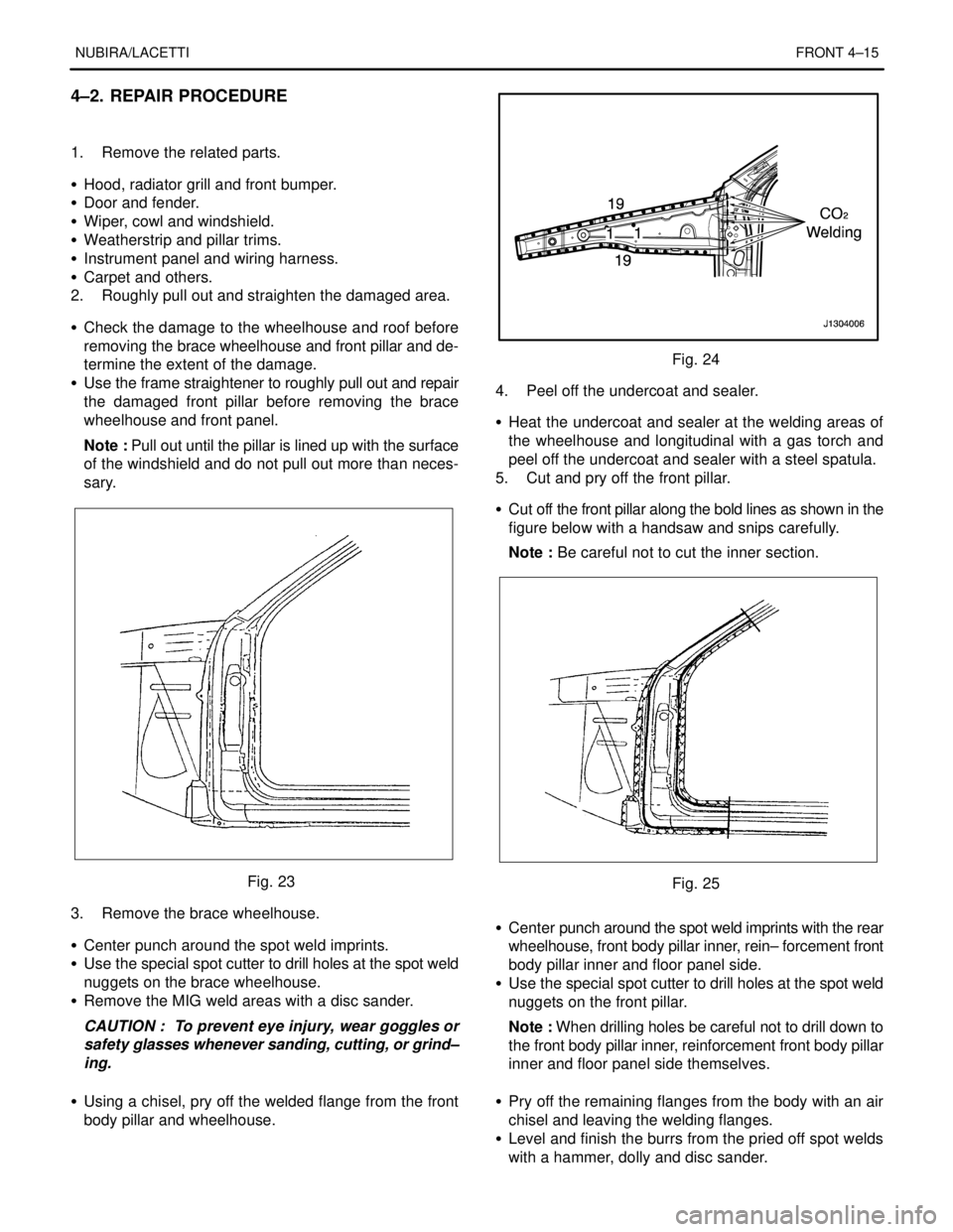
5. Cut and pry off the front pillar.
S Cut off the front pillar along the bold lines as shown in the
figure below with a handsaw and snips carefully.
Note : Be careful not to cut the inner section.
Fig. 25
S Center punch around the spot weld imprints with the rear
wheelhouse, front body pillar inner, rein– forcement front
body pillar inner and floor panel side.
S Use the special spot cutter to drill holes at the spot weld
nuggets on the front pillar.
Note : When drilling holes be careful not to drill down to
the front body pillar inner, reinforcement front body pillar
inner and floor panel side themselves.
S Pry off the remaining flanges from the body with an air
chisel and leaving the welding flanges.
S Level and finish the burrs from the pried off spot welds
with a hammer, dolly and disc sander.
Page 2551 of 2643
NUBIRA/LACETTIFRONT 4–17
Fig. 28
9. Finish the welding areas.
S Level the gas or MIG welded areas with a disc sander,
then even out high areas with a hammer being careful
not to deform them.
CAUTION : To prevent eye injury, wear goggles or
safety glasses whenever sanding cutting or grind-
ing.
S Use a hammer and dolly to even out the spot welded
flanges for a close fit with the surface of the inner panel.
S Fill in deformations and level differences of the welded
areas with solder or putty, then finish.
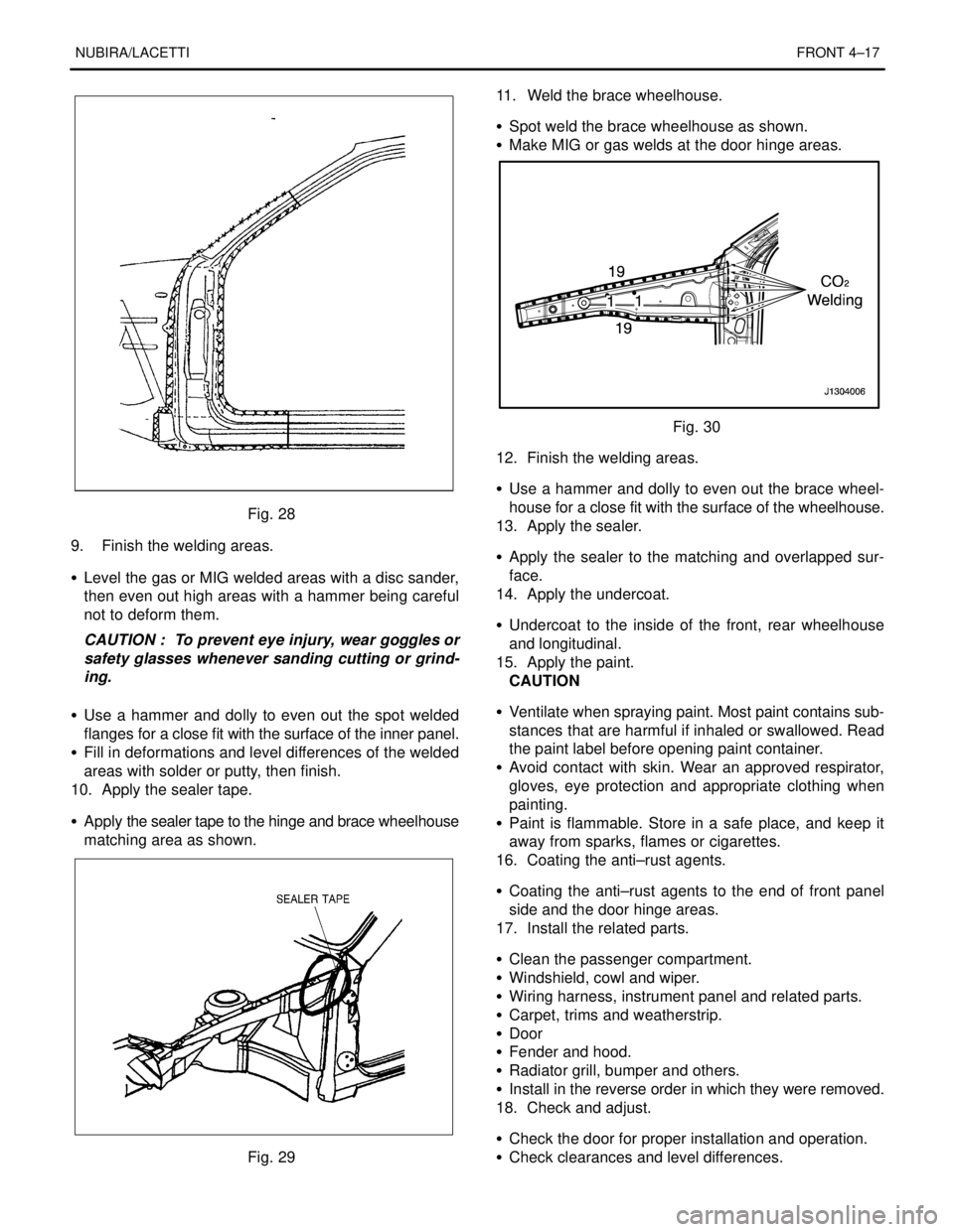
10. Apply the sealer tape.
S Apply the sealer tape to the hinge and brace wheelhouse
matching area as shown.
Fig. 2911. Weld the brace wheelhouse.
S Spot weld the brace wheelhouse as shown.
S Make MIG or gas welds at the door hinge areas.
Fig. 30
12. Finish the welding areas.
S Use a hammer and dolly to even out the brace wheel-
house for a close fit with the surface of the wheelhouse.
13. Apply the sealer.
S Apply the sealer to the matching and overlapped sur-
face.
14. Apply the undercoat.
S Undercoat to the inside of the front, rear wheelhouse
and longitudinal.
15. Apply the paint.
CAUTION
S Ventilate when spraying paint. Most paint contains sub-
stances that are harmful if inhaled or swallowed. Read
the paint label before opening paint container.
S Avoid contact with skin. Wear an approved respirator,
gloves, eye protection and appropriate clothing when
painting.
S Paint is flammable. Store in a safe place, and keep it
away from sparks, flames or cigarettes.
16. Coating the anti–rust agents.
S Coating the anti–rust agents to the end of front panel
side and the door hinge areas.
17. Install the related parts.
S Clean the passenger compartment.
S Windshield, cowl and wiper.
S Wiring harness, instrument panel and related parts.
S Carpet, trims and weatherstrip.
S Door
S Fender and hood.
S Radiator grill, bumper and others.
S Install in the reverse order in which they were removed.
18. Check and adjust.
S Check the door for proper installation and operation.
S Check clearances and level differences.
Page 2555 of 2643
NUBIRA/LACETTI ROOF, BACK PANEL AND REAR FLOOR PANEL 5–3
1–2. REPAIR PROCEDURE
1. Remove the related parts.
S Room lamp, door weatherstrip and pillar trims.
S Headlining and wiring harness.
S Wiper, cowl and windshield.
S Rear glass and others.
2. Pull out and straighten the damaged area to approxi-
mately the original shape.
Note : Use heat–resistant protective cover for protect
painting areas, seats, carpets and other parts.
S Attach the car to the frame straightener by tightening the
underbody clamps at the horizontal pinch welds.
S Before cutting off the roof panel, pull them out so that
they are restored to the original shape.
S Do not pull out more than necessary.
S Pull out and straighten the related damaged parts to
approximately their original shape.
Note : Make sure that the right and left pillars are parallel
with the windshield surface. Check the door for proper
opening and closing.
3. Keep the body, level.
S Jack up the body, and place safety stands at the four
designated places of the frame door opening.
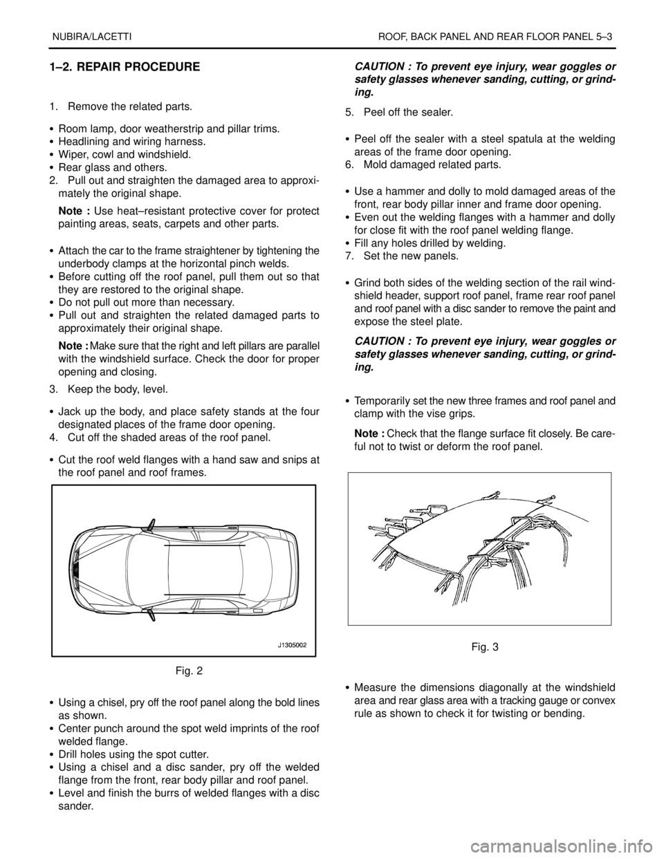
4. Cut off the shaded areas of the roof panel.
S Cut the roof weld flanges with a hand saw and snips at
the roof panel and roof frames.
Fig. 2
S Using a chisel, pry off the roof panel along the bold lines
as shown.
S Center punch around the spot weld imprints of the roof
welded flange.
S Drill holes using the spot cutter.
S Using a chisel and a disc sander, pry off the welded
flange from the front, rear body pillar and roof panel.
S Level and finish the burrs of welded flanges with a disc
sander.CAUTION : To prevent eye injury, wear goggles or
safety glasses whenever sanding, cutting, or grind-
ing.
5. Peel off the sealer.
S Peel off the sealer with a steel spatula at the welding
areas of the frame door opening.
6. Mold damaged related parts.
S Use a hammer and dolly to mold damaged areas of the
front, rear body pillar inner and frame door opening.
S Even out the welding flanges with a hammer and dolly
for close fit with the roof panel welding flange.
S Fill any holes drilled by welding.
7. Set the new panels.
S Grind both sides of the welding section of the rail wind-
shield header, support roof panel, frame rear roof panel
and roof panel with a disc sander to remove the paint and
expose the steel plate.
CAUTION : To prevent eye injury, wear goggles or
safety glasses whenever sanding, cutting, or grind-
ing.
S Temporarily set the new three frames and roof panel and
clamp with the vise grips.
Note : Check that the flange surface fit closely. Be care-
ful not to twist or deform the roof panel.
Fig. 3
S Measure the dimensions diagonally at the windshield
area and rear glass area with a tracking gauge or convex
rule as shown to check it for twisting or bending.
Page 2557 of 2643
NUBIRA/LACETTI ROOF, BACK PANEL AND REAR FLOOR PANEL 5–5
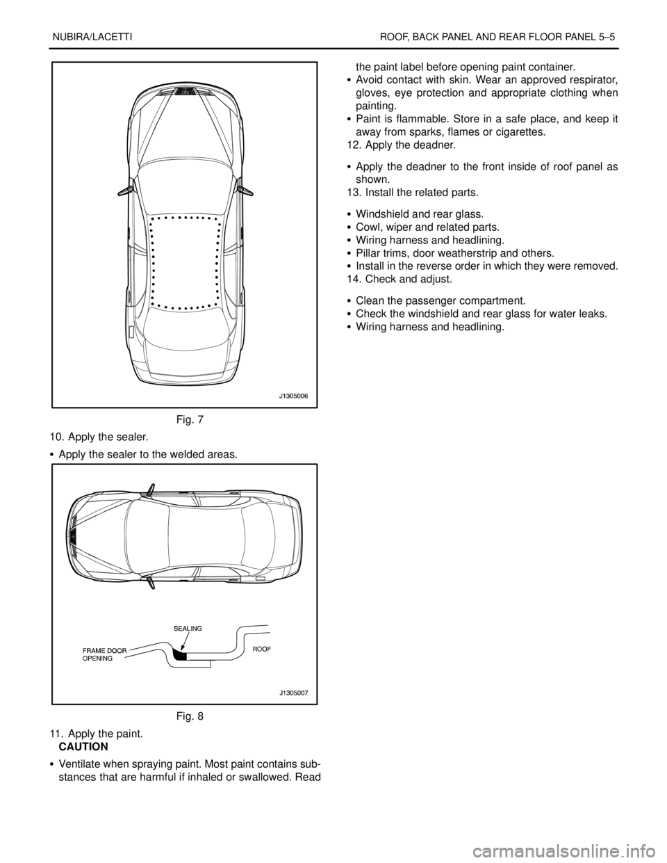
Fig. 7
10. Apply the sealer.
S Apply the sealer to the welded areas.
Fig. 8
11. Apply the paint.
CAUTION
S Ventilate when spraying paint. Most paint contains sub-
stances that are harmful if inhaled or swallowed. Readthe paint label before opening paint container.
S Avoid contact with skin. Wear an approved respirator,
gloves, eye protection and appropriate clothing when
painting.
S Paint is flammable. Store in a safe place, and keep it
away from sparks, flames or cigarettes.
12. Apply the deadner.
S Apply the deadner to the front inside of roof panel as
shown.
13. Install the related parts.
S Windshield and rear glass.
S Cowl, wiper and related parts.
S Wiring harness and headlining.
S Pillar trims, door weatherstrip and others.
S Install in the reverse order in which they were removed.
14. Check and adjust.
S Clean the passenger compartment.
S Check the windshield and rear glass for water leaks.
S Wiring harness and headlining.
Page 2581 of 2643
7–4 FENDER, HOOD, TAILGATE AND TRUNK LID NUBIRA/LACETTI
3. TAILGATE (HATCHBACK)
3–1. REPAIR PROCEDURE
1. Remove the related parts.
S Wiring harness.
S Rear wiper arm and motor.
S Rear window glass.
S Lock set, latch and others.
.
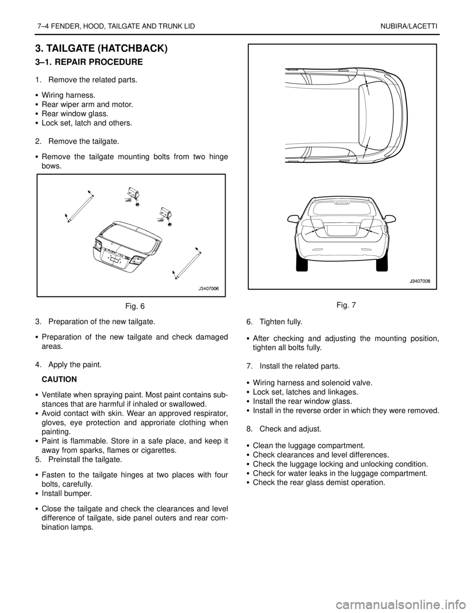
2. Remove the tailgate.
S Remove the tailgate mounting bolts from two hinge
bows.
Fig. 6
3. Preparation of the new tailgate.
S Preparation of the new tailgate and check damaged
areas.
.
4. Apply the paint.
CAUTION
S Ventilate when spraying paint. Most paint contains sub-
stances that are harmful if inhaled or swallowed.
S Avoid contact with skin. Wear an approved respirator,
gloves, eye protection and approriate clothing when
painting.
S Paint is flammable. Store in a safe place, and keep it
away from sparks, flames or cigarettes.
5. Preinstall the tailgate.
S Fasten to the tailgate hinges at two places with four
bolts, carefully.
S Install bumper.
S Close the tailgate and check the clearances and level
difference of tailgate, side panel outers and rear com-
bination lamps.Fig. 7
6. Tighten fully.
S After checking and adjusting the mounting position,
tighten all bolts fully.
.
7. Install the related parts.
S Wiring harness and solenoid valve.
S Lock set, latches and linkages.
S Install the rear window glass.
S Install in the reverse order in which they were removed.
.
8. Check and adjust.
S Clean the luggage compartment.
S Check clearances and level differences.
S Check the luggage locking and unlocking condition.
S Check for water leaks in the luggage compartment.
S Check the rear glass demist operation.