Page 1304 of 2643

(PIN NO. COLOR)
CONNECTING, WIRING HARNESSCONNECTOR POSITION
C")
5–144WELECTRICAL WIRING DIAGRAMS
20. REAR WINDOW DEFROSTER & OSRV MIRROR HEATING SYSTEM
CIRCUITa. CONNECTOR INFORMATION
CONNECTOR(NO.)
(PIN NO. COLOR)
CONNECTING, WIRING HARNESSCONNECTOR POSITION
C101 (21 Pin, White)Body � Engine Fuse BlockEngine Fuse Block
C102 (11 Pin, White)Body � Engine Fuse BlockEngine Fuse Block
C201 (76 Pin, Black)I.P � I.P Fuse BlockI.P Fuse Block
C202 (89 Pin, White)I.P � BodyLeft CO–Driver Leg Room
C208 (15 Pin, White)I.P � FAT CBehind Glove Box
C209 (20 Pin, Black)FAT C � FAT C . A u xBetween Heater Core and Evaporator Core
C351 (33 Pin, Gray)Body � Front Light DoorUnder CO–Driver A Pillar
C361 (33 Pin, Gray)Body � Front Right DoorUnder Driver A Pillar
C404 (8 Pin, White)T/Gate. EXT. � BodyInside Left C Pillar
C405 (8 Pin, White)T/Gate. EXT. � T/GateBeside Left Rear Wiper Motor
C406 (6 Pin, White)T/Gate. EXT. � T/GateBeside Left Rear Wiper Motor
S302 (Brown)BodyLeft CO–Driver Leg Room
G301BodyBelow Driver Cross Member Floor Panel
G303BodyBelow Left CO–Driver Leg Room
G402T/Gate. EXT.Inside Driver C Pillar
b. CONNECTOR IDENTIFICATION SYMBOL & PIN NUMBER POSITION
Page 1316 of 2643
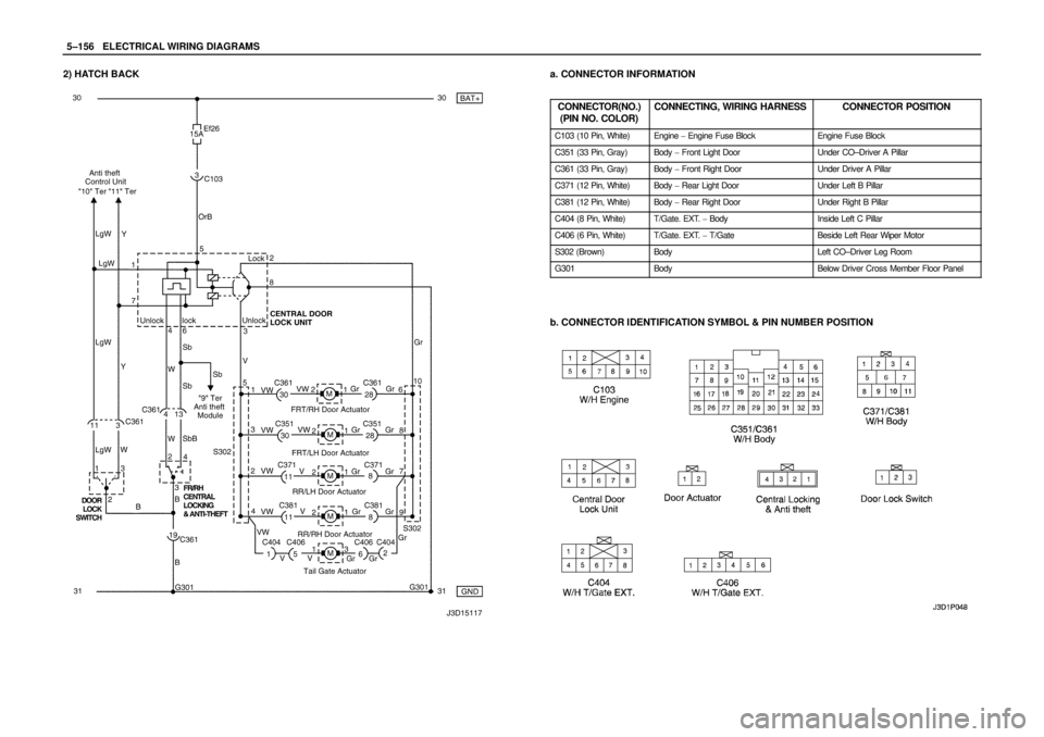
5–156WELECTRICAL WIRING DIAGRAMS
2) HATCH BACKa. CONNECTOR INFORMATION
CONNECTOR(NO.)
(PIN NO. COLOR)
CONNECTING, WIRING HARNESSCONNECTOR POSITION
C103 (10 Pin, White)Engine � Engine Fuse BlockEngine Fuse Block
C351 (33 Pin, Gray)Body � Front Light DoorUnder CO–Driver A Pillar
C361 (33 Pin, Gray)Body � Front Right DoorUnder Driver A Pillar
C371 (12 Pin, White)Body � Rear Light DoorUnder Left B Pillar
C381 (12 Pin, White)Body � Rear Right DoorUnder Right B Pillar
C404 (8 Pin, White)T/Gate. EXT. � BodyInside Left C Pillar
C406 (6 Pin, White)T/Gate. EXT. � T/GateBeside Left Rear Wiper Motor
S302 (Brown)BodyLeft CO–Driver Leg Room
G301BodyBelow Driver Cross Member Floor Panel
b. CONNECTOR IDENTIFICATION SYMBOL & PIN NUMBER POSITION
Page 1348 of 2643
 HATCH BACKa. CONNECTOR INFORMATION
CONNECTOR(NO.)
(PIN NO. COLOR)
CONNECTING, WIRING HARNESSCONNECTOR POSITION
C102 (11 Pin, White)Body � Engine Fuse BlockEngine")
5–188WELECTRICAL WIRING DIAGRAMS
2) HATCH BACKa. CONNECTOR INFORMATION
CONNECTOR(NO.)
(PIN NO. COLOR)
CONNECTING, WIRING HARNESSCONNECTOR POSITION
C102 (11 Pin, White)Body � Engine Fuse BlockEngine Fuse Block
C104 (24 Pin, White)Front � Engine Fuse BlockEngine Fuse Block
C105 (4 Pin, White)Body � Engine Fuse BlockEngine Fuse Block
C113 (16 Pin, Black)Body � FrontBehind ECM Bracket
C201 (76 Pin, Black)I.P � I.P Fuse BlockI.P Fuse Block
C202 (89 Pin, White)I.P � BodyLeft CO–Driver Leg Room
C351 (33 Pin, Gray)Body � Front Light DoorUnder CO–Driver A Pillar
C361 (33 Pin, Gray)Body � Front Right DoorUnder Driver A Pillar
C404 (8 Pin, White)T/Gate. EXT. � BodyInside Left C Pillar
C405 (8 Pin, White)T/Gate. EXT. � T/GateBeside Left Rear Wiper Motor
C406 (6 Pin, White)T/Gate. EXT. � T/GateBeside Left Rear Wiper Motor
S202 (Black)I.PBehind Cluster
S301 (Blue)BodyLeft CO–Driver Leg Room
S302 (Brown)BodyLeft CO–Driver Leg Room
G301BodyBelow Driver Cross Member Floor Panel
G302BodyBelow Left C Pillar
G303BodyBelow Left CO–Driver Leg Room
G402T/Gate. EXT.Inside Driver C Pillar
b. CONNECTOR IDENTIFICATION SYMBOL & PIN NUMBER POSITION
Page 1955 of 2643

SECTION : 6E
STEERING WHEEL AND COLUMN
CAUTION : Disconnect the negative battery cable before removing or installing any electrical unit or when a tool
or equipment could easily come in contact with exposed electrical terminals. Disconnecting this cable will help
prevent personal injury and damage to the vehicle. The ignition must also be in LOCK unless otherwise noted.
TABLE OF CONTENTS
SPECIFICATIONS6E–1 . . . . . . . . . . . . . . . . . . . . . . . . . .
Fastener Tightening Specifications 6E–1. . . . . . . . . . .
SPECIAL TOOLS6E–2 . . . . . . . . . . . . . . . . . . . . . . . . . . .
Special Tools Table 6E–2. . . . . . . . . . . . . . . . . . . . . . . .
DIAGNOSIS6E–2 . . . . . . . . . . . . . . . . . . . . . . . . . . . . . . . .
Steering Column Diagnosis 6E–2. . . . . . . . . . . . . . . . .
MAINTENANCE AND REPAIR6E–8 . . . . . . . . . . . . . . .
ON–VEHICLE SERVICE 6E–8. . . . . . . . . . . . . . . . . . . . .
Headlamp/Turn Signal Switch and Lever 6E–8. . . . . .
Wiper Switch and Lever 6E–9. . . . . . . . . . . . . . . . . . . . Steering Wheel Rotation Sensor 6E–10. . . . . . . . . . . .
Steering Wheel Without SIR 6E–11. . . . . . . . . . . . . . . .
Steering Wheel With SIR 6E–13. . . . . . . . . . . . . . . . . .
Ignition Lock Cylinder and Switch 6E–13. . . . . . . . . . .
Steering Column 6E–15. . . . . . . . . . . . . . . . . . . . . . . . . .
UNIT REPAIR 6E–19. . . . . . . . . . . . . . . . . . . . . . . . . . . . .
Tilt Steering Column 6E–19. . . . . . . . . . . . . . . . . . . . . .
GENERAL DESCRIPTION AND SYSTEM
OPERATION6E–20 . . . . . . . . . . . . . . . . . . . . . . . . . . . . .
Steering Wheel and Column 6E–20. . . . . . . . . . . . . . . .
Ignition Key Reminder 6E–20. . . . . . . . . . . . . . . . . . . . .
SPECIFICATIONS
FASTENER TIGHTENING SPECIFICATIONS
ApplicationNSmLb–FtLb–In
Ignition Switch Housing Shear Bolts11–97
Ignition Switch Retaining Screw2.5–22
Steering Column Jacket Assembly Front Bracket Bolts2216–
Steering Column Jacket Assembly Rear Bracket Nuts2216–
Steering Shaft Universal Joint Pinch Bolt2518–
Steering Wheel Horn Cap Screws4.5–40
Steering Wheel Nut3828–
Steering Wheel Rotation Sensor Retaining Screw2–18
Support Housing Screws1612–
Turn Signal Switch Housing Screws3–27
Upper and Lower Steering Column Cover Panel Screws2.5–22
Page 1961 of 2643

STEERING WHEEL AND COLUMN 6E – 7
DAEWOO V–121 BL4
Front or Rear Turn Signal Lights Not Flashing
ChecksAction
Check for a faulty turn signal switch.Replace the turn signal switch.
Check the chassis–to–column connector for an improper
connection.Reconnect the chassis–to–column connector.
Turn Signal Lights Flash Very Slowly
ChecksAction
Check the chassis–to–column connector for an improper
connection.Reconnect the chassis–to–column connector.
Ignition Switch
Electrical System Will Not Function
ChecksAction
Check the ignition switch for damage.Replace the ignition switch.
Check the ignition switch for improper installation.Remove and inspect the ignition switch. Reinstall the igni-
tion switch.
Check the ignition switch electrical connector for improper
installation.Reconnect the ignition switch electrical connector.
Replace the ignition switch electrical connector.
Ignition Switch Will Not Turn
ChecksAction
Check the ignition switch for damage.Replace the ignition switch.
Check the ignition switch for improper installation.Remove and inspect the ignition switch. Reinstall the igni-
tion switch.
Wiper Lever and Switch
Switch Inoperative: No LOW, HIGH, INTERMITTENT or WASH
ChecksAction
Check the wiper lever and switch for damage.Replace the wiper lever and switch.
Check the wiper lever and switch for improper installation.Remove and inspect the wiper lever and switch.
Reinstall the wiper lever and switch.
Page 1963 of 2643

STEERING WHEEL AND COLUMN 6E – 9
DAEWOO V–121 BL4
3. Install the upper and the lower steering column cov-
er panels. Install the upper and the lower steering
column cover panel screws.
Tighten
Tighten the upper and the lower steering column cov-
er panel screws to 2.5 NSm (22 lb–in).
4. Connect the negative battery cable.
WIPER SWITCH AND LEVER
(Left–Hand Drive Shown, Right–Hand Dirve
Similar)
Removal Procedure
1. Disconnect the negative battery cable.
2. Remove the upper and the lower steering column
cover panel screws.
3. Remove the upper and the lower steering column
cover panels.
4. Remove the wiper switch by pushing the tabs on
the top and the bottom of the switch housing.
5. Disconnect the electrical connector from the wiper
switch. Disconnect the cruise control connector, if
equipped.
Installation Procedure
1. Connect the electrical connector to the wiper
switch. Connect the cruise control connector, if
equipped.
2. Install the wiper switch by snapping it into the
switch housing.
Page 1969 of 2643

Important : Remove the steering column only if the follow-
ing conditions")
STEERING WHEEL AND COLUMN 6E – 15
DAEWOO V–121 BL4
STEERING COLUMN
(Left–Hand Drive Shown, Right–Hand Dirve
Similar)
Important : Remove the steering column only if the follow-
ing conditions exist:
S The steering column requires replacement.
S The steering and the ignition lock housing require
replacement.
S Another operation requires the removal of the
steering column.
Notice : The steering column is extremely susceptible to
damage after it has been removed from the vehicle. Drop-
ping the column assembly on its end or hammering the
end of the steering shaft can collapse the steering shaft or
loosen the plastic injections which maintain column rigid-
ity. Leaning on the column can cause it to bend or deform.
Any of the above damage can impair the column’s collaps-
ible design. If it is necessary to remove the steering wheel,
use only the specified steering wheel puller.
Removal Procedure
1. Disconnect the negative battery cable and let the
vehicle sit for 1 minute to deactivate the airbag.
2. Remove the the lower instrument trim panels. Refer
to Section 9E, Instrumentation/Driver Information.
3. Remove the upper and the lower steering column
cover panel by removing the screws.
4. Remove the switch levers. Refer to ”Turn Signal
Switch and Lever” and ”Wiper Switch and Lever” in
this section.
5. Remove the immobilizer module. Refer to Section
9T, Remote Keyless Entry and Anti–theft System.
6. Disconnect the airbag electrical connections.
Page 1972 of 2643
6E – 18ISTEERING WHEEL AND COLUMN
DAEWOO V–121 BL4
6. Connect the ignition switch electrical connection.
7. Connect the airbag electrical connections.
8. Install the switch levers. Refer to ”Turn Signal
Switch and Lever” and ”Wiper Switch and Lever” in
this section.
9. Install the immobilizer module. Refer to Section 9T,
Remote Keyless Entry and Anti–theft System.
10. Install the lower instrument trim panels. Refer to
Section 9E, Instrumentation/Driver Information.
11. Install the upper and the lower steering column cov-
er panel with the screws..
Tighten
Tighten the upper and the lower steering column pan-
el screws to 2.5 NSm (22 lb–in).
12. Inspect the steering wheel in a straight–ahead posi-
tion. Refer to Section 6C, Power Steering Gear.
13. Connect the negative battery cable.